

In this article
- Key takeaways
- What is a double torsion spring?
- Why are the two bodies wound in opposite directions?
- The two load cases
- How to calculate rate, torque and stress
- Leave room for the coils to wind up
- Designing the centre loop and legs
- Materials and finishes
- Double torsion spring calculator
- What to put on the drawing or request for quote
- Frequently asked questions
- About the authors
- Sources
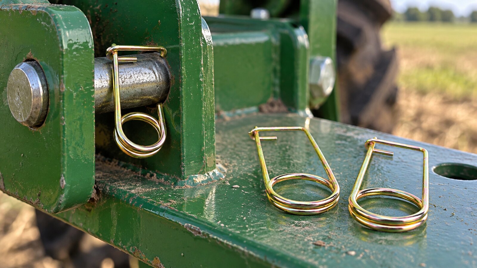
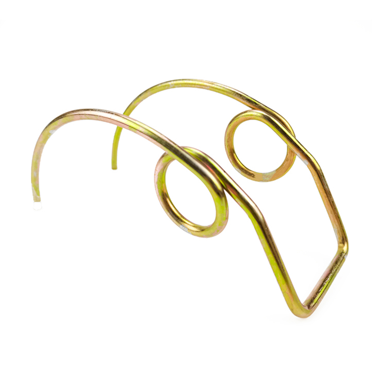
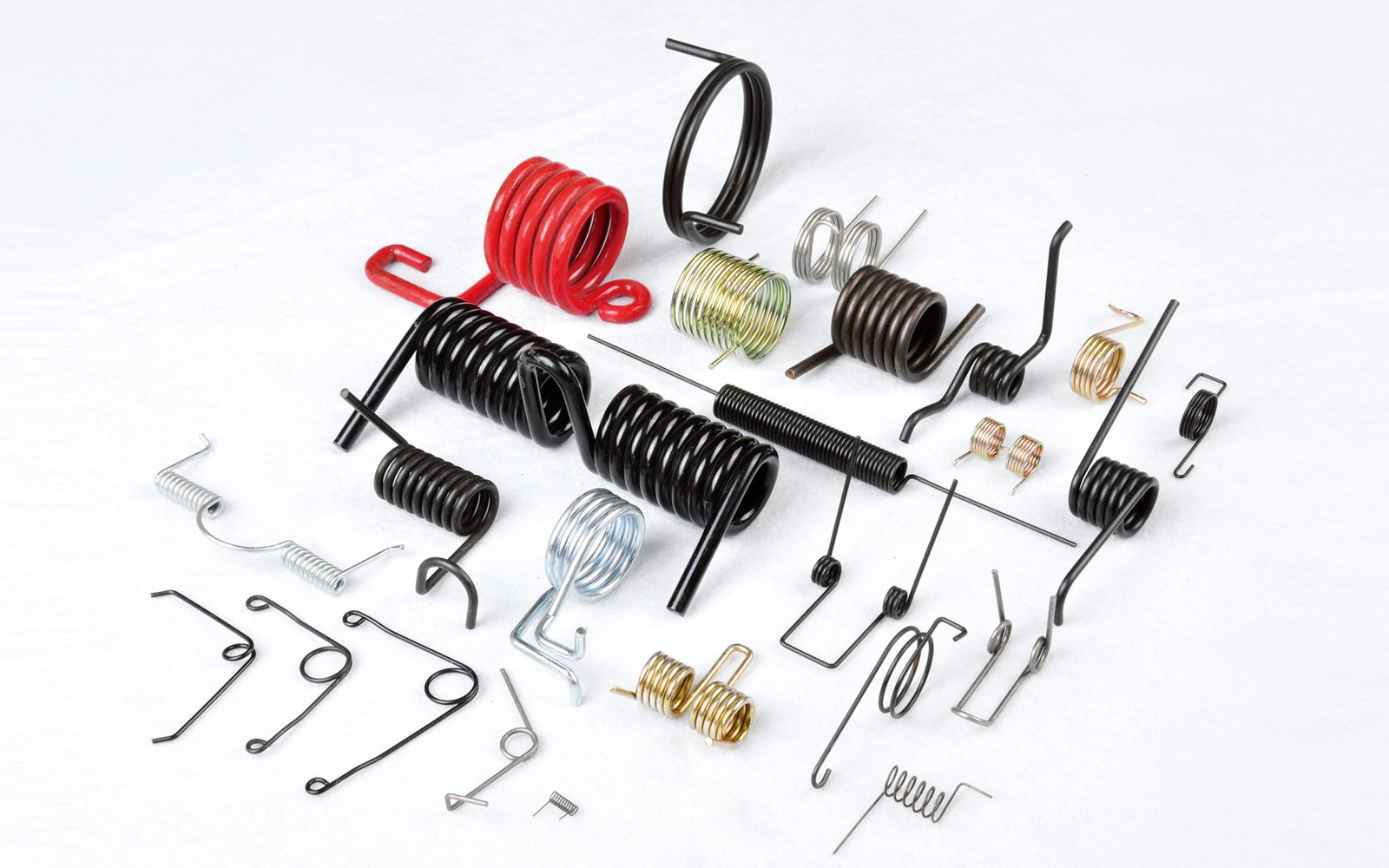
A double torsion spring is one length of wire wound into two coil bodies, one left-hand and one right-hand, joined in the middle by a U-shaped centre loop (often called the hairpin), with a leg at each outer end. It gives a balanced torque across a wide part from a single spring, and it is the usual form for baler pickup, rake and tedder spring tines.
The two halves look like a single torsion spring and its mirror image, and that is how they are calculated. What changes is how the load reaches them. This guide explains the two ways a double torsion spring is usually loaded, how to work out its rate, torque and stress, how much room the coils need as they wind up, and what to put on a drawing. A free double torsion spring calculator runs the numbers for both load cases.
Key takeaways
- The bodies are opposite hand so both wind up together. A torsion spring should be loaded in the direction that closes its coils. Mirror-image bodies make that true on both sides.
- Know your load case. If the centre loop is loaded and the legs are held, the halves work in parallel and the torque adds. If the loop is clamped and each leg is loaded separately, as on spring tines, each half works alone.
- Calculate each half as a single torsion spring. Rate per turn k = d⁴E / (10.8·D·Na), with the legs added to the active coils as (l1 + l2)/(3πD).
- Leave room for wind-up. In our example the inside diameter closes from 19.0 to 18.4 mm at 60°, so the arbor should be no larger than about 16.6 mm. Each body also grows about 0.5 mm in length.
- Specify torque at a working angle and the hand of each body. Both halves have to match, so coil count and leg angle tolerances matter more than on a single spring.
What is a double torsion spring?
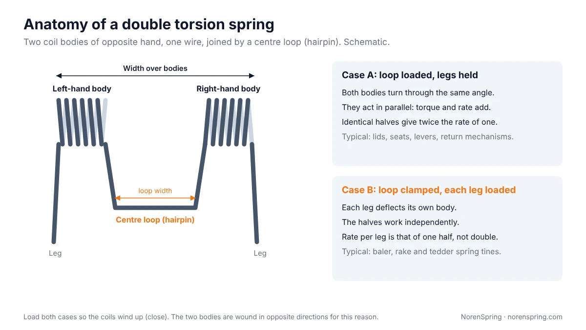
A double torsion spring (also called a double-bodied or double coil torsion spring) has two helical torsion bodies made from one continuous wire. The bodies are wound in opposite directions, one right-hand and one left-hand, and they are joined by a length of wire, usually bent into a U or a flat bridge, between them [3][4]. The outer ends of the wire form the two legs.
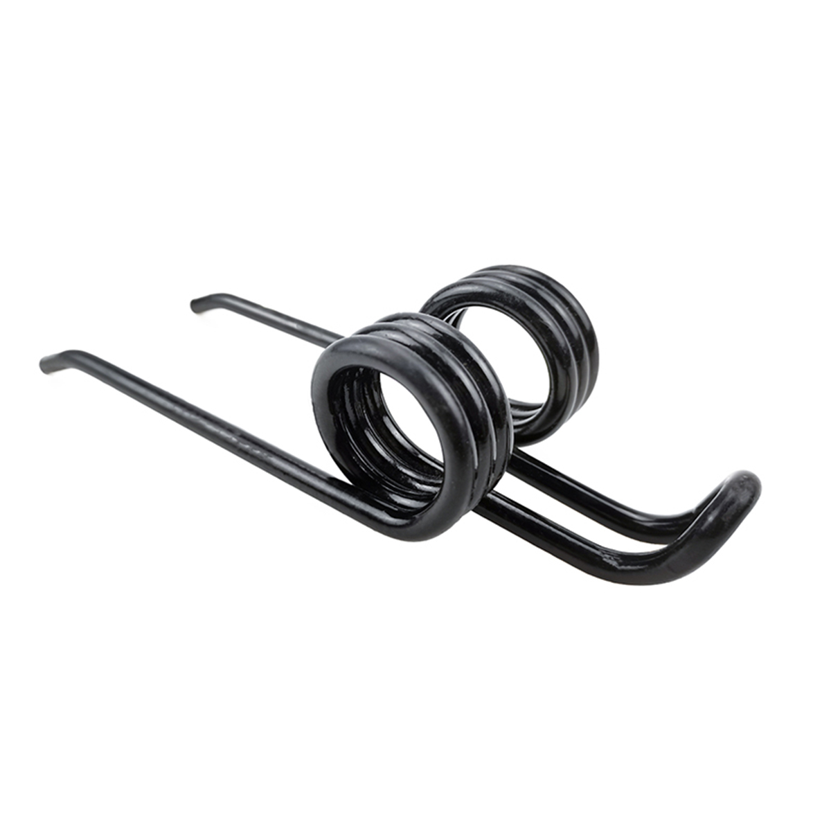
Compared with a single torsion spring, a double torsion spring:
- Balances the load across the part. The torque is applied at two points, so a lid, lever or tine bar is pushed evenly rather than twisted to one side.
- Doubles the torque in the same coil diameter when both halves work together, because their torques add [3][4].
- Gives two working teeth from one part when each leg is loaded on its own, which is why it suits spring tines.
The trade-off is that both halves must match. A difference of a quarter coil or a few degrees of leg angle between the two sides shows up directly as an uneven load.
Why are the two bodies wound in opposite directions?
A torsion spring works best when the load winds up the coils, that is, when it closes them and reduces their diameter. Loaded the other way, the coils open and the maximum safe load is lower [5]. Spring makers’ guidance agrees [3].
In a double torsion spring the two legs, or the two sides of the centre loop, move the same way. If both bodies were wound the same hand, one of them would be unwinding. Making them mirror images means both close together. When you send a sample or drawing, mark the hand of each body; getting one side wrong produces a part that fits but fails early. Our spring tines guide shows how to tell left-hand from right-hand on a sample.
The two load cases
How the spring is held and loaded decides whether its halves add up or work alone.
Case A: the centre loop is loaded and the legs are held. This is the classic double torsion spring in lids, seats, levers and return mechanisms. The legs rest against the frame, the loop pushes on the moving part (or the reverse), and both bodies turn through the same angle. They act like two springs in parallel, so their rates and torques add [3][4]. With identical halves, the whole spring has twice the rate of one half.
Case B: the centre loop is clamped and each leg is loaded on its own. This is how baler pickup tines, rake tines and tedder tines work. The loop is bolted or clamped to the tine bar or rotor arm, and each leg is a tooth that deflects when it meets crop, ground or a stone. Each body carries only its own tooth’s load, so the rate at each tooth is the rate of one half, not double. The spring tines guide covers tines in detail, and our torsion spring case studies show tines and torsion parts we make.
Other arrangements exist, such as one leg fixed and the other loaded through the loop. In every case, work out which part of the wire is held, where the load enters, and which way each body turns.
How to calculate rate, torque and stress
No standard we found gives a separate formula for double torsion springs; EN 13906-3 covers cylindrical helical torsion springs [6]. The usual approach, which we use, is to treat each half as a single helical torsion spring and then combine the halves according to the load case. For each half:
1. Active coils. The legs also bend under load, so they add to the active coils [1][2]:
Na = Nb + (l1 + l2) / (3πD)
where Nb is the number of body coils, D the mean coil diameter (OD − d), l1 the outer leg length from the coil centre to the load point, and l2 the centre-loop arm from the coil centre to where the load is applied (in case B, to the clamp). Counting the loop arm as the second leg is our application of the single-spring formula to a double spring.
2. Rate. Per turn of deflection, with the friction allowance Shigley recommends for a spring working over an arbor [1][2]:
k = d⁴E / (10.8 · D · Na) (N·mm per turn, with E in MPa and lengths in mm)
Divide by 360 for N·mm per degree. Shigley notes that the theoretical constant of 10.2 is raised to 10.8 because tests show friction between the coils and the arbor [2].
3. Combine the halves. In case A, add the two rates and torques. In case B, use one half’s rate for each leg.
4. Stress. The wire in a torsion spring is in bending, not torsion. The highest stress is at the inside of the coil [2]:
σ = Kᵢ · 32M / (πd³), with Kᵢ = (4C² − C − 1) / (4C(C − 1)) and C = D/d
where M is the moment carried by that half. See our spring index guide for how C affects this factor.
Worked example
A double torsion spring for a return mechanism, load case A:
- Wire d = 3.0 mm, body OD = 25 mm, so D = 22 mm and C = 7.33.
- 6 body coils per side, outer legs 40 mm, centre-loop arm 25 mm per side.
- Carbon spring steel, E = 200 GPa. Working (and maximum) angle 60°.
| Step | Result |
|---|---|
| Active coils per side, Na = 6 + 65 / (3π × 22) | 6.31 |
| Rate of one half, k = 3⁴ × 200,000 / (10.8 × 22 × 6.31) | 30.0 N·mm/° (10.80 N·m per turn) |
| Rate of whole spring (two halves in parallel) | 60.0 N·mm/° |
| Torque of whole spring at 60° | 3.60 N·m |
| Force on the loop at the 25 mm arm | 144 N |
| Inner-fibre factor Kᵢ at C = 7.33 | 1.11 |
| Bending stress in each body, M = 1.80 N·m | 756 MPa |
If the same spring were used as a tine (case B), each leg would see 1.80 N·m at 60°, or about 45 N at the 40 mm leg tip, and the stress in each body would be the same 756 MPa. In case B, take l2 as the distance from the coil centre to the clamp; the example assumes 25 mm.
Whether 756 MPa is acceptable depends on the wire grade and size, whether the load is static or cyclic, and the cycle life you need. These are calculations, not test results; we can check them against the wire’s allowable stress before quoting.
Leave room for the coils to wind up
As a torsion spring winds up, each turn gets slightly smaller and the body gets slightly longer. Shigley gives the loaded mean diameter as [1]:
D′ = Nb · D / (Nb + θc)
where θc is the deflection of the body coils in turns. In the worked example, at 60° the inside diameter of each body closes from 19.00 mm to 18.43 mm.
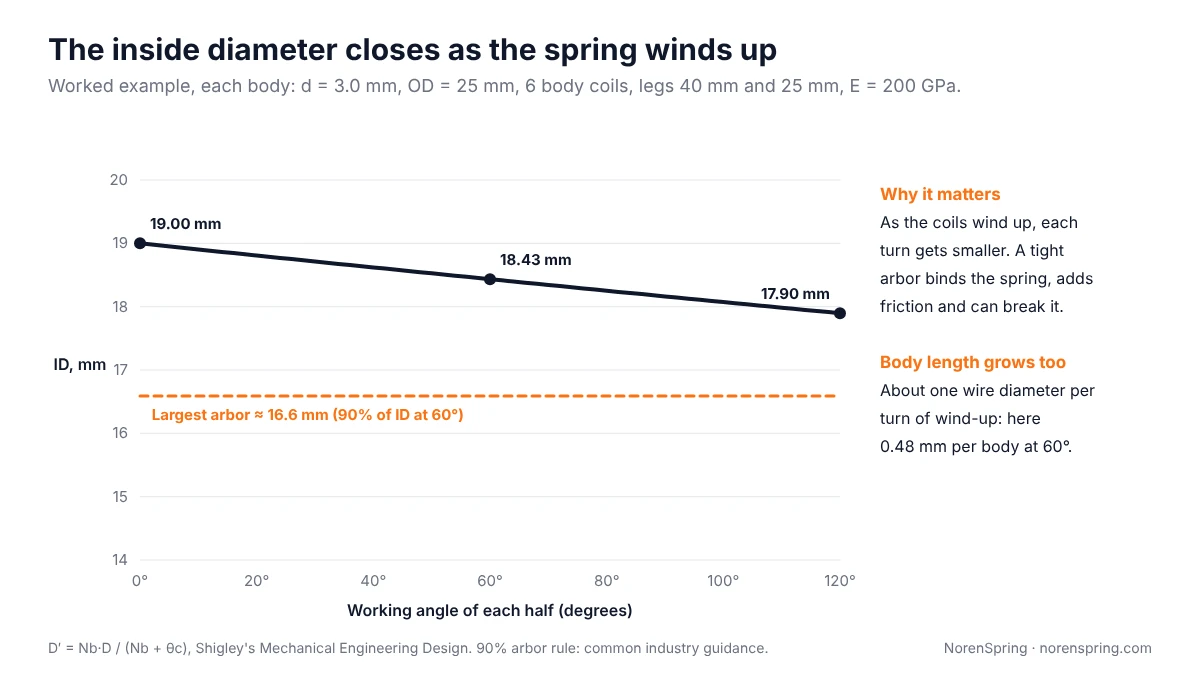
- Arbor size. Shigley gives the diametral clearance to a pin as Δ = D′ − d − Dp, and it must stay positive [1][2]. A common rule is to make the arbor or shaft no more than about 90% of the inside diameter at full deflection, that is, about 10% clearance [3][5]. Use the largest angle the spring ever reaches, including during assembly. Here, at 60°, that is about 16.6 mm. A tight arbor binds the coils, adds friction, changes the torque and can break the spring.
- Body length. Each body grows by roughly one wire diameter for every full turn of deflection [3][5]. Here that is about 0.48 mm per body at 60°. In a double torsion spring both bodies grow, so allow side clearance at the outer ends of the bodies and at the centre loop.
Designing the centre loop and legs
The centre loop and legs are where most of the drawing detail, and many of the failures, are.
- Loop width and shape. The loop sets the distance between the bodies and how the spring locates on the part. Give its inside width and length, and say which surface it bears on. On tines, the loop must fit the clamp or bolt on the tine bar.
- Bend radii. Bends concentrate stress, so the bend where the leg leaves the coil is a typical fatigue crack site on tines. Avoid sharp inside radii; a bend radius of at least the wire diameter is a reasonable starting point to discuss.
- Leg length and angle. Give the free angle between each leg and the loop, and the working angle at which you need the torque. Long legs bend too, which is why they are counted in the active coils.
- Symmetry. State whether the two halves are identical or mirrored with different leg lengths, as on some tedder tines.
Materials and finishes
Double torsion springs are made from the same wires as single torsion springs: carbon spring steel and oil-tempered wire for most industrial parts, alloy spring steels for heavy, cyclic loads, and stainless steel where corrosion matters. Our spring wire material guide compares the grades.
Heavy agricultural double torsion tines are usually made from high-carbon or alloy spring steel and then coated. One example from our production is a double torsion tine in 10 mm 65Mn spring steel, hardened to 42–47 HRC, with two coils of 45 mm diameter and a black polymer coating to RAL 9005 [7]. For outdoor parts, see the spring finishes guide; zinc plated springs are baked after plating to reduce the risk of hydrogen embrittlement.
Double torsion spring calculator
Double torsion spring calculator
Two identical bodies of opposite hand, round wire. Gives the rate and torque, bending stress, how far the inside diameter closes, and the largest arbor to use.
Estimates from Shigley’s Mechanical Engineering Design: rate k = d⁴E / (10.8·D·Na) per turn with Na = Nb + (l1 + l2)/(3πD), bending stress with the inner-fibre factor Kᵢ, and loaded diameter D′ = Nb·D / (Nb + θc). Each half is treated as a single torsion spring; the centre loop arm is counted as that half’s second leg. The arbor figure uses the common 90% rule. Send the design to us to check the stress against your wire grade before ordering.
What to put on the drawing or request for quote
- Wire diameter and material (grade or standard).
- Hand of each body, confirming they are opposite.
- Body coils per side, including the partial turn.
- Body inside or outside diameter, and the arbor or shaft diameter it works on.
- Centre loop: inside width, length and shape, and which surface carries the load.
- Legs: length, shape, bends and end forms, with the free angle of each.
- Load case: whether the loop or the legs are loaded, and which way the spring winds.
- Torque at one or two working angles, with a tolerance, and whether it is measured at the loop or at the legs.
- Space limits: width over the bodies at full deflection, and any parts close to the legs.
- Finish, cycle life and quantity.
If you have a sample rather than a drawing, send it. We can measure it, calculate its rate, and confirm a drawing with you before samples are made. Most of our projects start from a customer drawing or sketch, and we can also work from a physical sample. We confirm manufacturability before quoting. See our torsion springs range, the general custom torsion spring guide for single-body design, or send your inquiry through the contact page.
Frequently asked questions
What is the difference between a single and a double torsion spring?
A single torsion spring has one coil body and two legs. A double torsion spring has two coil bodies of opposite hand joined by a centre loop, with a leg at each outer end. The double form balances the load across a wider part and, when both halves work together, gives twice the torque in the same coil diameter.
How do you calculate the torque of a double torsion spring?
Calculate each half as a single torsion spring, using k = d⁴E / (10.8·D·Na) per turn and Na = Nb + (l1 + l2)/(3πD). Multiply the rate by the working angle to get each half’s torque. If the centre loop is loaded and the legs held, add the two torques. If each leg is loaded separately, each leg sees one half’s torque.
Which way should a double torsion spring be loaded?
In the direction that winds up, or closes, the coils of both bodies. That is why the bodies are wound in opposite directions.
How much clearance does a double torsion spring need on its arbor?
Size the arbor from the inside diameter at full deflection, not the free inside diameter. A common rule is to make the arbor no larger than about 90% of that loaded inside diameter. Also allow for each body growing in length by about one wire diameter per turn of deflection.
Are spring tines double torsion springs?
Baler pickup, rake and tedder tines are usually double torsion springs. The centre loop is clamped to the machine and each leg is a tooth with its own coil. See our spring tines guide for measuring and replacing them.
Can the two halves have different numbers of coils?
They can, for example when a part needs a different torque on each side, but each half is then calculated separately and the drawing must show the coils for each. Most double torsion springs use identical halves.
About the authors
This guide was prepared by the NorenSpring engineering team, which designs and manufactures custom springs and wire forms in Xuzhou, China. Technical review by Feng Yulin, General Manager and senior structural engineer, who has 15 years of spring R&D experience and more than 30 national patents. NorenSpring holds IATF 16949, ISO 9001, ISO 13485, ISO 14001 and ISO 45001 certifications. More about NorenSpring. How this guide was prepared: the formulas follow Shigley’s Mechanical Engineering Design and are cited to the sources below, and the worked example, the figures and the calculator were each computed separately and checked against one another. Figures and calculations were last checked on 13 October 2026.
Sources
The numbers in square brackets in the text refer to this list.
- Engineers Edge, Torsion spring coil deflection and diameter reduction, reproducing the helical torsion spring equations from Shigley’s Mechanical Engineering Design. Source for the rate per turn with the 10.8 constant, the active coil allowance for legs and the loaded diameter D′ = Nb·D / (Nb + θc). Retrieved 2026-10-13.
- R. G. Budynas and J. K. Nisbett, Shigley’s Mechanical Engineering Design, McGraw-Hill, chapter 10 (Mechanical Springs), and the publisher’s chapter 10 lecture slides. Source for the bending stress and inner-fibre factor Kᵢ, the raising of 10.2 to 10.8 for arbor friction, and the requirement that the coil must not close onto its pin. Retrieved 2026-10-13.
- Century Spring, Double Torsion Springs and Select a Torsion Spring (manufacturer guidance). Source for the hairpin description, the torque of the two coils adding, the preferred wind-up direction, the body growing about one wire diameter per turn and the 90% mandrel rule. Retrieved 2026-10-13.
- Katy Spring, Double-bodied torsion springs (manufacturer guidance). Source for the right-hand and left-hand coil sections working in parallel to double the torque output. Retrieved 2026-10-13.
- Engineers Edge, Torsion spring design calculator notes. Source for designing torsion springs to wind in the direction of the coil winding and for the diameter reduction and length growth under load. Retrieved 2026-10-13.
- CEN, EN 13906-3:2014, Cylindrical helical springs made from round wire and bar — Calculation and design — Part 3: Torsion springs, scope at Genorma. European calculation standard for single-body helical torsion springs. Retrieved 2026-10-13.
- NorenSpring production records: the 65Mn double torsion tine example, as confirmed by our factory in October 2026.