

In this article
- Key Takeaways
- Define the load path for spring retaining clips
- Mating dimensions and assembly access
- How should insertion and retention forces be specified?
- Material and finish requirements
- What should the sample validation plan include?
- Build a complete quotation package
- Frequently Asked Questions
- Build the enquiry around the assembled function
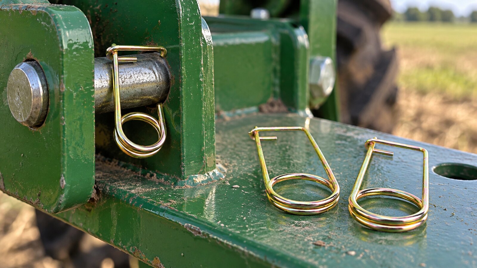
Cover image: an AI illustration based on a real photo of our part, not a photograph of a customer installation.
Specify wire spring clips around the parts they retain: the mating geometry, the direction of possible escape, and the forces allowed during installation and removal. A clip that looks correct on a drawing can still be difficult to assemble or easy to dislodge if those conditions are missing.
This guide is for engineers and buyers purchasing wire retainers for equipment assemblies. It concentrates on proving fit and retention, rather than repeating a general wire-bending design guide. The aim is a purchase specification that the supplier, assembly team and incoming inspector can all interpret in the same way.
Key Takeaways
- Specify the clip and its mating parts together. Wire diameter alone does not define a reliable retaining assembly.
- Installation force, resistance to accidental release and deliberate removal force are different acceptance requirements.
- Validate the assembly at the relevant tolerance limits and in its intended service environment.
- Agree the inspection method and lot records before ordering. A visually matching sample is not a complete specification.
Define the load path for spring retaining clips
A wire spring clip holds a component in its intended position by elastic engagement with a mating feature. Begin by identifying what must not move, in which direction, and what happens if the clip releases.
For a pin-and-retainer arrangement, the main pin may carry the working load while the clip prevents that pin from moving out of its hole. Those duties are not interchangeable. Do not assign the main joint load to a small retainer simply because both parts appear in the same assembly.
Draw the load path from the retained part through the joint. Then mark the possible escape path separately. This makes the distinction visible to the person quoting the clip and to the engineer approving the assembly. If the clip itself carries a structural load, state that explicitly and require an application-specific assessment.
Use a part description, not just a familiar name
Names such as R-clip, hairpin clip and spring retainer are useful search terms, but they do not replace an approved drawing. Different suppliers may use a familiar name for parts with different contact shapes, lengths or mating-pin ranges.
The DIN 11024 catalogue entry identifies spring cotters. If that standard applies to your purchase, state the required designation and edition and check the licensed requirements. The public catalogue entry alone is not enough to reconstruct a dimension table or claim compliance.
Also distinguish spring clips from split cotter pins. The NASA Fastener Design Manual illustrates cotter-pin locking of a castellated nut. That is a specific locking arrangement, not permission to replace its cotter with any removable spring clip. Follow the equipment drawing when a particular locking method is required.
Mating dimensions and assembly access
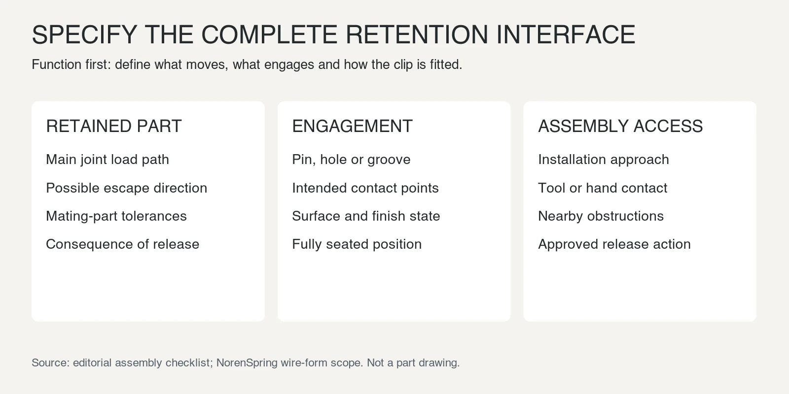
The enquiry needs the geometry that the clip touches and the space through which it must move. Include the mating pin or shaft, any hole or groove, nearby surfaces and the available installation access.
Send an assembly section as well as the loose-part drawing. Identify the intended contact points. A dimension on the clip may be easy to inspect yet contribute little to retention; another feature may control engagement even though it looks less prominent. Inspection priorities should follow function.
Check the tolerance limits of the assembly
Do not validate only the nominal mating part. The smallest permitted pin, largest hole, deepest groove or thinnest panel may affect engagement differently from the opposite tolerance condition. Which combination matters depends on the design; it should be identified by the responsible engineer rather than assumed from a generic rule.
Include finish thickness where it affects contact or clearance. Check whether paint buildup, burrs, edge radii or coating damage can change how the clip seats. The drawing should distinguish a functional edge from an incidental manufacturing edge.
A practical review asks whether the clip can reach its final position, whether it remains engaged there, and whether it can be removed by the intended method. A successful installation on one sample does not answer all of those questions across production tolerances.
Show the access and orientation
Specify the approach direction and any restriction on rotation. A clip may fit when the assembly is open but become inaccessible after a cover or adjacent component is installed. Include the assembly sequence if it changes access.
State whether fitting is by hand, a fixture or a specified tool. Do not solve poor access by increasing force without reviewing what else is being loaded. The same instruction applies to removal: the service technician needs a defined release method that does not require bending the clip beyond its intended movement.
How should insertion and retention forces be specified?
Specify separate acceptance conditions for installation, unintended release and deliberate removal. A single requirement such as “tight fit” cannot tell an inspector which action to test or where to apply the load.
Installation force concerns getting the clip into its fully seated position. Retention concerns resisting a defined disturbance while seated. Deliberate removal concerns releasing the part by the approved action. Their directions, contact points and fixtures may differ, so one result cannot automatically stand in for another.
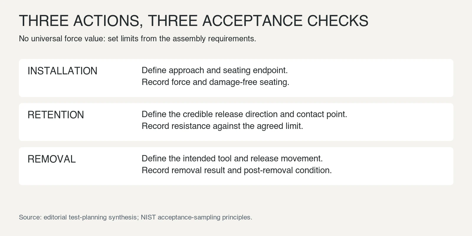
| Check | Define before testing | Record |
|---|---|---|
| Installation | Approach, tool contact, mating condition and seating endpoint | Force result and whether the clip seated without damage |
| Retention | Load direction, contact location and allowed movement | Result against the agreed release or displacement limit |
| Removal | Intended release action and permitted tool | Removal result and condition of the clip and mating part |
| Reuse | Whether reuse is allowed and the application-specific test sequence | Engagement and condition after the agreed sequence |
If accidental contact can catch an exposed loop, include that concern in the risk review. A pull in the intended removal direction may be much more important than a larger load in a direction that never releases the clip. The correct test is the one that represents the credible disturbance.
State whether the requirement is a peak force, a force at a position, or resistance to a load without disengagement. Use newtons for force and identify the displacement reference where needed. Avoid mixing a mass description with a force requirement unless the test method defines the conversion and loading arrangement.
Material and finish requirements
Material and finish must support the required elastic movement and the service environment while preserving fit. They should be agreed together with the geometry, not selected after sample approval as a cosmetic change.
Describe exposure to moisture, chemicals, temperature and cleaning. State whether the clip touches a finished cosmetic surface or an electrically sensitive interface. These details help the supplier assess suitable options without inventing a performance claim from a material name.
A stainless designation alone does not establish corrosion life in every environment. Equally, the appearance of a plated sample does not prove coating performance. Specify the required material designation, finish and acceptance evidence, then request confirmation of suitability for the actual exposure.
Where clip deformation is significant, the supplier needs to assess forming and material condition. Keep that discussion linked to the functional requirements. The existing wire forms design guide covers bend geometry and manufacturability; this acceptance plan adds the assembled retention checks.
NorenSpring de-embrittles all zinc-plated springs by hydrogen-relief baking after plating. Specify the required finish and associated records at enquiry stage so that post-plating treatment remains part of the documented process. This treatment is not a substitute for checking the finished clip against the assembly acceptance requirements.
A documented agricultural clip example
The wire-form application cases include zinc R-pin clips for agricultural machinery for a customer in Thailand. Customer drawings and test limits are confidential.
For a comparable enquiry, supply the mating-pin details, installation access and required retention behaviour. Agree the inspection conditions and documentation before sample approval.
As a general-practice scenario: on a harvester or baler linkage, the exposed loop of an R-clip can catch on crop material. In that case, test retention in the direction the crop drags the loop, not only straight along the pin axis.
Retaining parts we already make
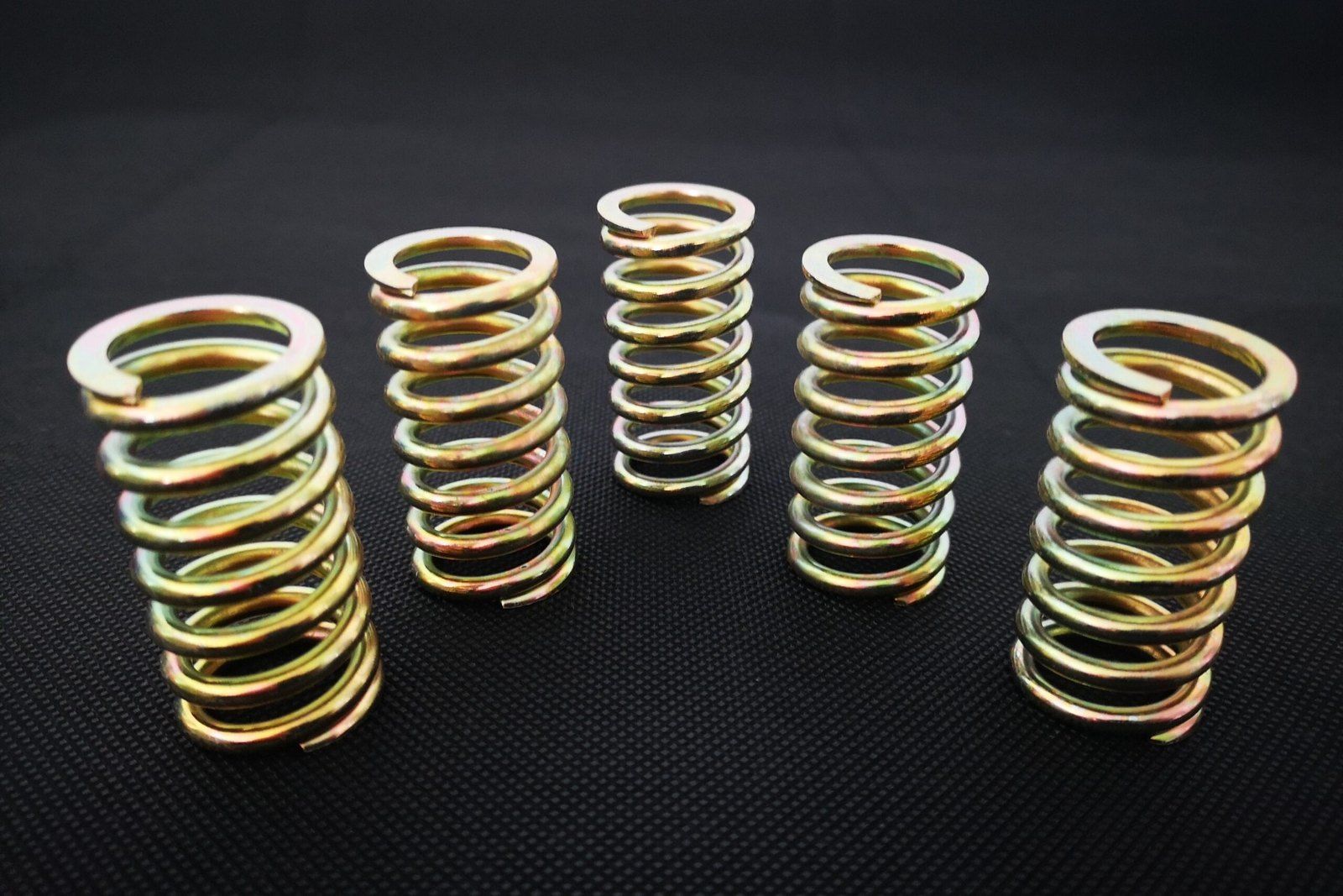
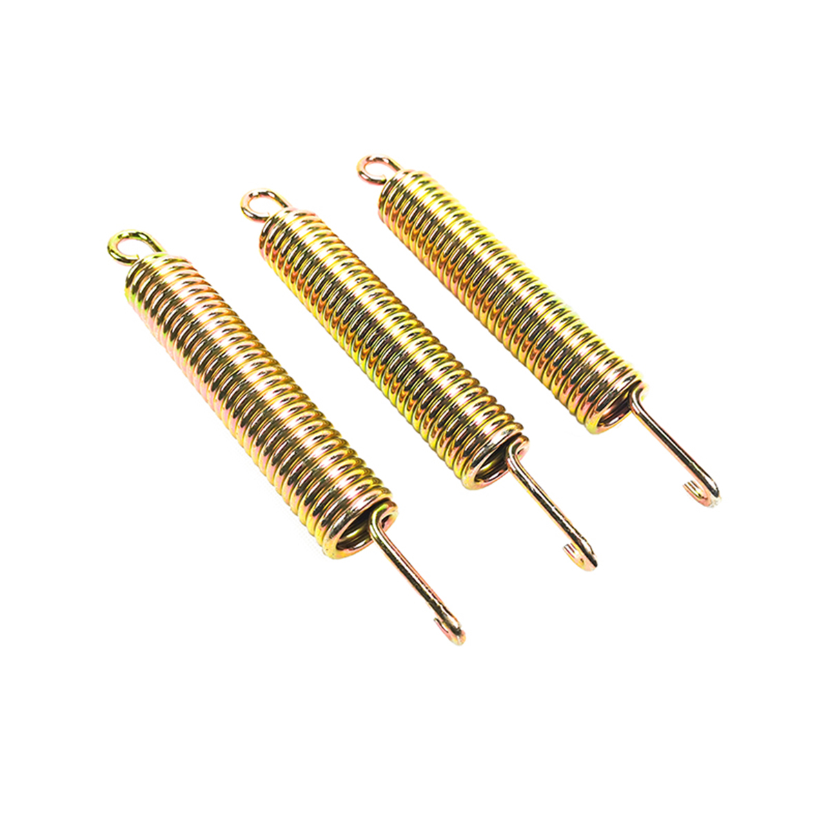
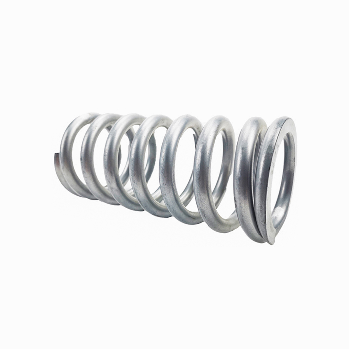
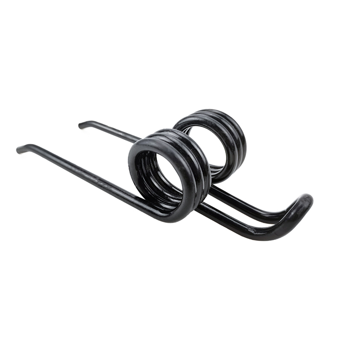
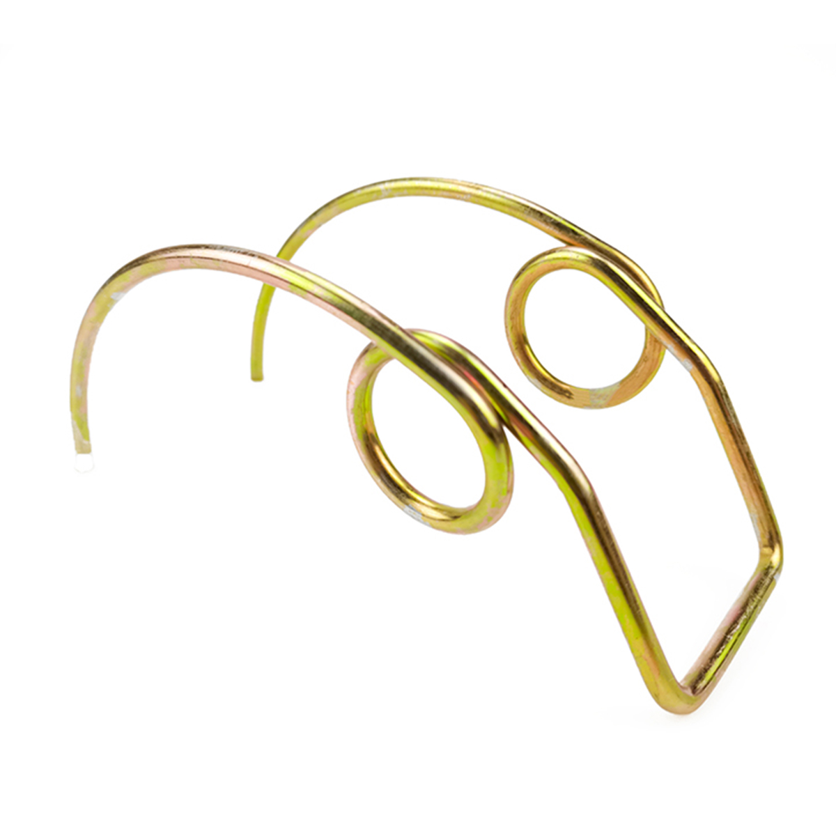
Our wire forms range includes spring steel circlips, steel retaining springs and steel spring clips, alongside harvester and harrow tines. Finishes seen on parts we have supplied include zinc and nickel plating, phosphate, black oxide, powder coating, painting and passivation for SUS304 stainless springs. For a clip on outdoor machinery, the finish choice and the de-embrittlement step after zinc plating belong in the same conversation as the retention test.
What should the sample validation plan include?
The validation plan should test the actual interface under agreed conditions and produce a clear accept, reject or engineering-review decision. Approve the method before treating a sample result as evidence for production release.
Begin with identified samples and mating parts. Record their drawing revisions, material and finish condition. If a master fixture replaces the real assembly, document what it represents and where it differs. A rigid fixture may be useful for repeatable comparison but may not reproduce a flexible panel or a worn service joint.
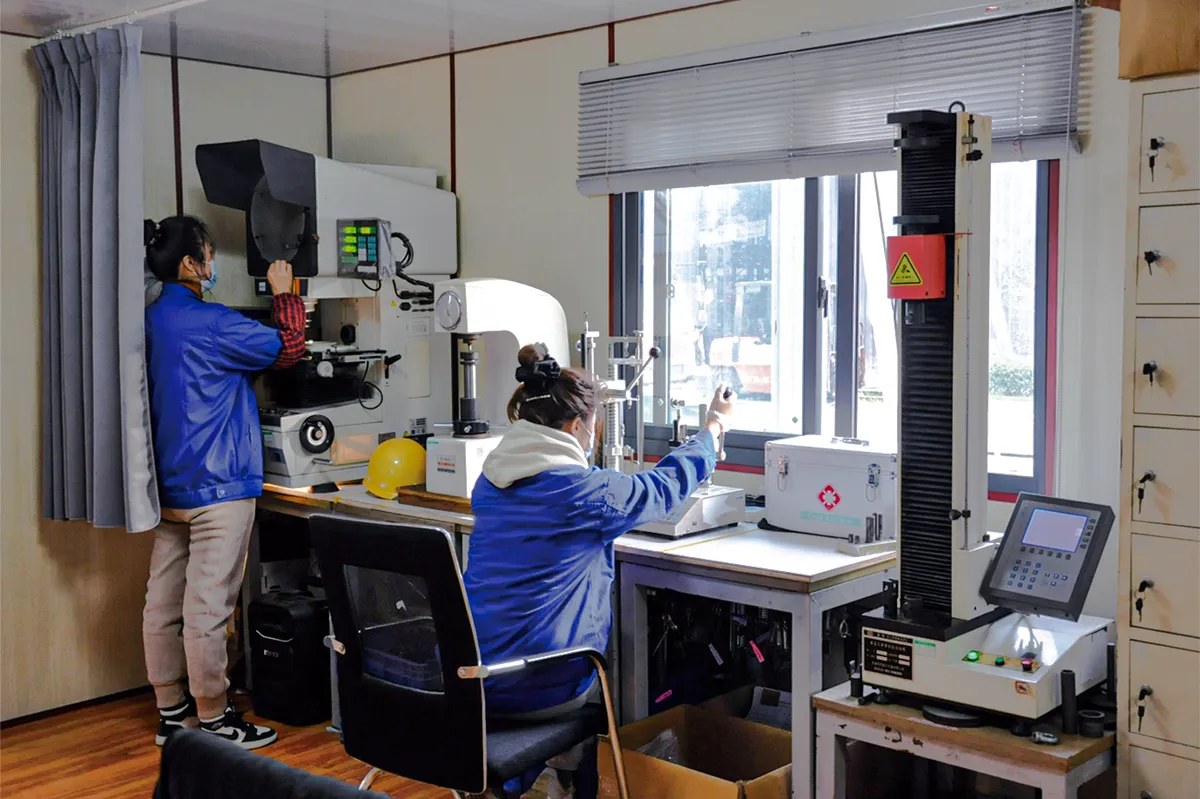
For force checks, define alignment, movement rate and the point at which the result is taken. Use a measurement system appropriate to the force range and the acceptance margin. Keep operator technique from becoming an unrecorded variable.
Include realistic use without inventing a lifetime
If removal and reuse are part of the application, agree the reuse sequence and acceptance conditions with the assembly engineer. If the clip is intended for single installation, do not advertise it as reusable because a sample can be removed and refitted.
Service validation may also need vibration, contamination, temperature or corrosion exposure. The need and conditions depend on the equipment. Do not substitute a generic endurance claim for this work, and do not assume that a supplier’s routine dimensional inspection includes every application test.
Run the agreed sample check in order
- Confirm sample identity, drawing revision and the mating-part tolerance condition.
- Install the clip by the intended method and record the specified installation result.
- Apply the agreed retention check in the defined escape direction.
- Remove the clip if removal is required, then inspect the clip and mating feature for permanent opening, damage or incomplete seating.
- Compare the recorded results with the approved limits and document acceptance or engineering review.
Separate sample approval from lot acceptance
A prototype approval establishes that the submitted design and samples meet the agreed checks. It does not mean every future shipment has been inspected. Production needs its own control and acceptance arrangement.
The NIST explanation of acceptance sampling distinguishes a decision about a lot from estimating its overall quality. Agree the lot definition, sample selection, acceptance criteria and response to a failed check. Do not choose a convenient handful of parts and describe it as a statistical guarantee.
Build a complete quotation package
Request a quotation against a controlled functional package: the clip drawing, mating interface, acceptance method and required records. This reduces the chance that competing quotations cover different parts or different inspection obligations.
- Clip and assembly drawings with revisions and units.
- Mating-part tolerances, contact surfaces and installation access.
- Required material and finish, or clearly identified items for supplier review.
- Separate installation, retention and removal requirements.
- Quantity, packaging needs and identification requirements.
- Sample approval plan, production acceptance method and requested reports.
- Change-control requirements for geometry, material, finish and process changes affecting function.
Use the wire forms product page to confirm the relevant product family, but keep the purchase order tied to the approved specification. A catalogue photograph or broad product title is not a substitute for the revision you intend to buy.
For incoming inspection, check identification before testing. Keep accepted and rejected lots separate, record any concession and retain the evidence behind it. If a nonconforming clip is accepted for a limited purpose, that approval should not silently become the standard for later orders.
Frequently Asked Questions
Is an R-clip interchangeable with a split cotter pin?
Not automatically. They use different retention arrangements. Use the locking method required by the assembly drawing and obtain engineering approval before substitution, especially where release could create a safety hazard.
Can a supplier quote from an existing sample?
A sample can start the discussion, but it does not show all original tolerances, material requirements or service conditions. Supply the mating parts and explain the function so that the eventual drawing and acceptance plan are controlled.
Should the tightest clip always be selected?
No. Excess installation or removal force can damage the assembly or make service impractical. The correct clip meets the agreed retention requirement while remaining compatible with the permitted fitting and release methods.
Can every wire spring clip be reused?
No universal reuse claim is appropriate. Reuse depends on the design, material condition, installation movement and service damage. State whether reuse is required and validate it against the intended application before approving it.
Build the enquiry around the assembled function
For custom spring clips, send the clip drawing, mating-part details and required retention checks through NorenSpring’s engineering enquiry. Identify any unresolved limits as questions for review. Agreeing those limits before production is more useful than approving a loose clip that merely resembles the old part.
NorenSpring has an in-house testing laboratory and IATF 16949 certification. Samples are available for dimensional, load and application approval, with engineering feedback within 24 hours. Confirm the project-specific checks and required records when submitting the enquiry.