

In this article
- Key takeaways
- The main types of spring failure
- Fatigue failure (fatigue fracture)
- Set, sag and relaxation: when a spring loses force
- Corrosion and corrosion fatigue
- Hydrogen embrittlement
- Overload and solid stress
- Buckling, coil clash and wear
- Surge and resonance in dynamic springs
- Hook and leg failures in extension and torsion springs
- How to investigate a broken spring
- Prevention checklist for your drawing and RFQ
- Have a spring that keeps failing?
- Frequently asked questions
- About the authors
- Sources
Spring failure takes one of two forms: the spring breaks, or it loses force and gets shorter. Breakage is nearly always fatigue, a crack that grows a little with every load cycle until the wire snaps. Corrosion pits, surface defects, hydrogen from plating or resonance often start or speed up that crack. Force loss is set or relaxation: the spring yields slightly when it is overstressed, or creeps when it is hot. ASM’s failure analysis handbook lists four root causes behind spring failures: design deficiencies, material defects, processing errors and unusual operating conditions. In most cases, it says, these end in fatigue [1].
This guide explains how to recognise each failure mode, what usually causes it, and how to prevent it. It covers compression, extension and torsion springs and wire forms in industrial, agricultural and automotive use. It finishes with a step-by-step way to investigate a broken spring and a checklist for your next drawing or quote.
Key takeaways
- Fatigue is the end point of most spring failures. A fatigue crack usually starts at the surface, most often on the inside of the coil where the stress is highest, unless a defect or corrosion pit starts it somewhere else.
- A spring that gets shorter has taken a set. The cause is stress above the material’s limit, heat, or both. Presetting during manufacture and a lower design stress prevent it.
- Corrosion shortens fatigue life far more than it reduces static strength. A small pit can start a crack at a stress the spring would otherwise survive indefinitely.
- Plated high-strength springs need hydrogen relief. Electroplating can put hydrogen into the steel and cause delayed brittle fracture. Baking soon after plating, as the plating specification requires, reduces the risk.
- Keep the broken pieces. The fracture surface tells you more than anything else. Do not fit the ends back together or clean them with a wire brush.
The main types of spring failure
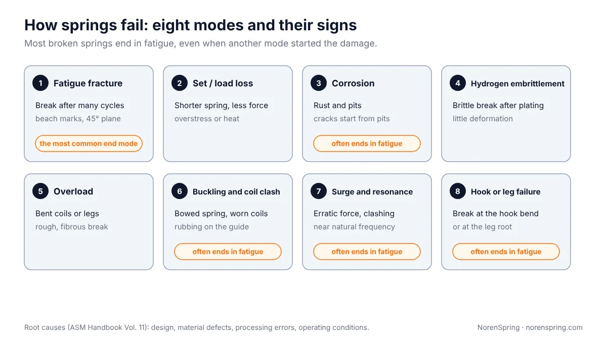
The table below summarises the failure modes in this guide. Each has its own section with causes and prevention.
| Failure mode | What you see | Usual causes | Main prevention |
|---|---|---|---|
| Fatigue fracture | Break after many cycles; smooth zone with beach marks, then a rough final zone | Stress range too high; surface defects; no shot peening; decarburization | Lower stress range, shot peening, good wire surface |
| Set and load loss | Spring shorter than new; less force at the installed length | Stress above the elastic limit; heat; no presetting | Lower stress, presetting, a material rated for the temperature |
| Corrosion and corrosion fatigue | Rust, pits; cracks starting from pits | Wrong material or finish for the environment; damaged coating | Stainless or a protective finish, drainage, inspection |
| Hydrogen embrittlement | Brittle break soon after plating or assembly, often with little load | Hydrogen absorbed during pickling or electroplating | Hydrogen relief baking after plating, or a non-electrolytic finish |
| Overload | Bent coils or legs, a sudden ductile break | Load or travel beyond design; spring pressed solid | Design stress at solid, mechanical stops |
| Buckling, coil clash, wear | Bowed spring, worn coils, polished marks on the guide | Slender spring, poor guidance, rubbing | Lower L0/D, guide rod or tube, clearance |
| Surge and resonance | Erratic force, coil clash, early fatigue breaks | Operating near the spring’s natural frequency | Natural frequency 15 to 20 times the operating frequency |
| Hook or leg failure | Break at the hook bend or at the leg root | Stress concentration at tight bends | Larger bend radius, reduced-diameter end coils, stress relief |
Fatigue failure (fatigue fracture)
Spring fatigue failure is the most common way for a spring to break [1]. A crack starts at a point of high stress, grows a little on every cycle, and the wire finally snaps when the remaining section cannot carry the load.
How to recognise it. The break follows many cycles of normal service, not a single overload. In a compression or extension spring the wire is loaded in torsion, so the fracture typically runs at about 45° to the wire axis. The surface shows a smooth region with curved “beach marks” spreading from the origin, and a rougher region where the final break happened. ASM describes valve springs with exactly this pattern: torsional fatigue fractures with beach marks at 45° to the wire axis [2].
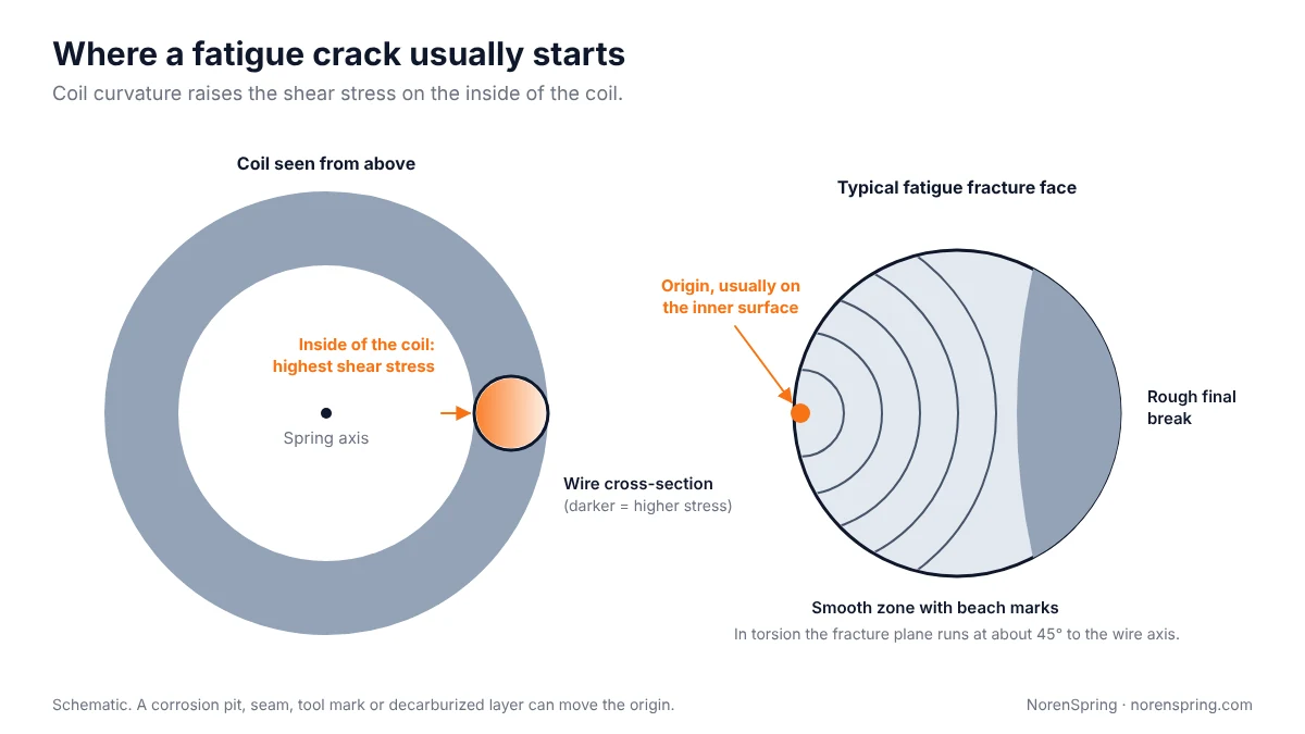
Where it starts. The shear stress in a helical spring is highest on the inside of the coil, because the curvature of the wire concentrates it there. That is why designers apply the Wahl or Bergsträsser correction factor [3], which grows as the spring index gets smaller. ASM’s case histories describe the inner surface as the usual fatigue origin. When a crack starts elsewhere, the cause is usually a defect: a surface lobe on a valve spring whose shot blasting had not done its job, or a pocket of inclusions with partial decarburization below the surface [2][4].
Common causes.
- Stress range too high for the material and surface condition. The alternating stress, not just the peak stress, controls fatigue. See the fatigue step of our compression spring design guide.
- Surface defects. Seams, scratches, tool marks from coiling and inclusions near the surface all start cracks early.
- Decarburization. A soft, carbon-depleted skin on the wire lowers fatigue strength. In tests on SUP6 spring steel, a decarburized layer 0.19 mm deep halved the fatigue life [5]. Volvo and Chalmers researchers note that decarburization limits are usually 0.1 to 0.2 mm, and that up to 0.5 mm has been seen in production [6].
- No shot peening on a highly cycled spring.
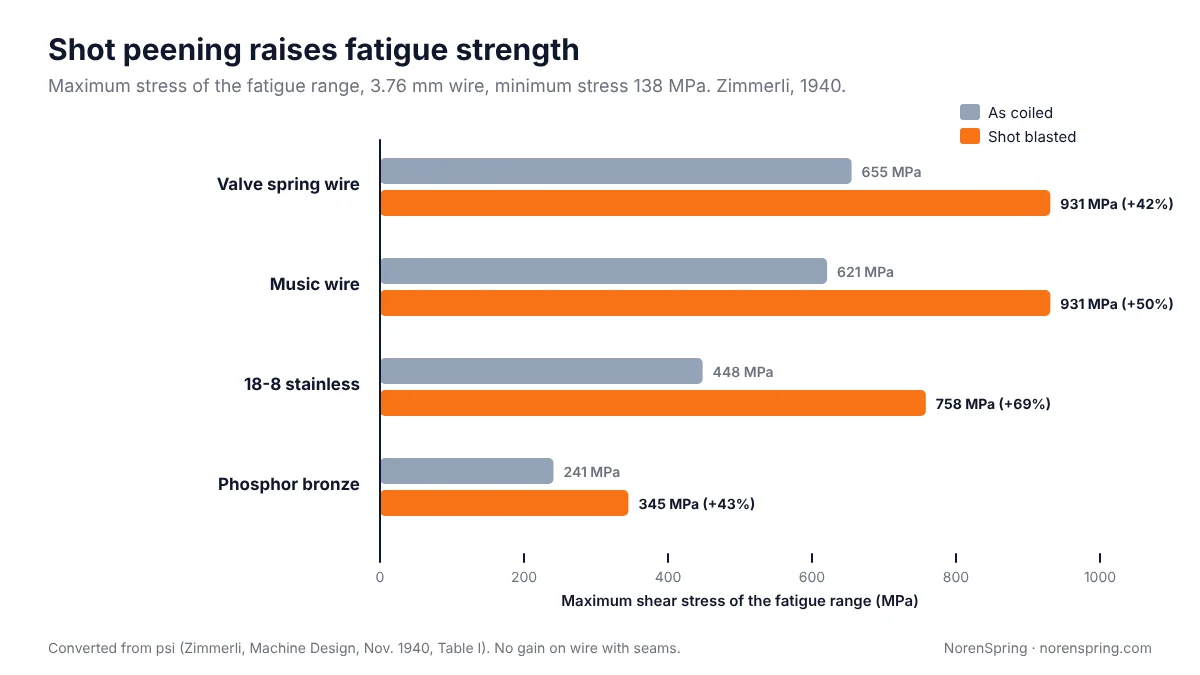
Prevention. Lower the stress range with a larger wire or more active coils. Specify spring wire with a good surface and controlled decarburization; our spring wire material guide compares the grades. Shot peen springs that see high cycle counts. Our spring manufacturing process guide shows where shot peening, presetting and stress relief fit in production. Shot peening puts the wire surface into compression, which resists crack growth. Zimmerli’s original 1940 tests found the maximum fatigue stress of valve spring wire rose by about 42% after shot blasting [7]. In shot peening tests on decarburized 51SiCr7 spring steel, peening raised the fatigue limit by 45% [6]. Peening cannot rescue a wire with seams; Zimmerli found no improvement on wire with seams or hairline defects [7].
Set, sag and relaxation: when a spring loses force
A spring that is shorter than when it was new, or gives less force at its installed length, has taken a set. The machine still works, but the spring no longer holds the load it was designed for. A valve may not seal, a clutch may slip, or a tine may not hold the crop.
Why it happens. Two mechanisms are at work:
- Set from overstress. If the stress exceeds the material’s elastic limit, part of the deflection becomes permanent. This often happens when a spring is compressed to solid during assembly or misuse, and the spring was not designed to survive it.
- Relaxation over time. Under a constant load, stress relaxes slowly. The effect grows quickly with temperature and stress. A spring that is fine at room temperature can lose a significant part of its force near an engine or a heater.
Prevention.
- Design the stress at solid within the static limit for the material, or add a stop so the spring cannot reach solid.
- Preset the spring. Presetting, also called set removal, means making the spring longer than needed and compressing it to solid after coiling. The spring takes its set in the factory, and favourable residual stresses remain. Shigley describes removing 10% to 30% of the initial free length this way. Presetting raises the allowable static stress for music wire and cold-drawn carbon steel from about 45% of tensile strength to 60% to 70% [3]. Shigley also notes that set removal is not recommended for springs subject to fatigue [3].
- Choose the material for the temperature. Typical published maximum service temperatures are around 120 °C for music wire and hard-drawn wire and about 150 °C for oil-tempered carbon wire. They rise to about 220 to 245 °C for chrome-vanadium and chrome-silicon, and to roughly 260 to 290 °C for 302/304 stainless. Nickel alloys such as Inconel X-750 go well above that. These are rules of thumb from spring makers’ tables; our spring wire material guide gives the full table. Check the limit for your stress level with your supplier.
- Allow for some load loss in the design when the spring works hot or under constant load for years. Specify the force you need at the end of service, not only when the spring is new.
Corrosion and corrosion fatigue
Rust on a spring is more than a cosmetic problem. Corrosion pits act as notches, and a fatigue crack can start from a pit at a stress the spring would otherwise survive indefinitely.
How to recognise it. Rust or white zinc corrosion products, pits along the coils, and a fatigue fracture that starts from a pit. Damage often concentrates where water or mud collects, at the end coils and in contact areas.
Prevention.
- Choose the material for the environment. Stainless steel springs resist moisture but have lower strength and stiffness than carbon spring steel, so they need a larger wire for the same load.
- Protect carbon steel springs. Common finishes include zinc plating, zinc flake coatings, phosphate with oil, and powder or polymer coatings. Our spring finishes guide compares them.
- Protect the coating. A coating cracked by coil clash, or rubbed off where the spring touches its guide, is where corrosion starts.
- Design out water traps and inspect springs in wet, salty or fertiliser-laden service, such as agricultural machinery.
Hydrogen embrittlement
Hydrogen embrittlement causes brittle fractures in high-strength steel springs, often hours or days after plating or assembly and at loads well below normal. Hydrogen enters the steel during acid pickling and electroplating, collects at points of high stress and makes the steel brittle.
How to recognise it. A sudden break with little or no deformation, typically soon after the parts were plated or installed, often in several springs from the same batch. The fracture surface looks granular rather than showing fatigue beach marks.
Prevention.
- Bake after plating. A hydrogen relief heat treatment soon after electroplating lets the hydrogen diffuse out. ISO 9588 and ASTM B850 give procedures for it and say it should be done after plating and before any secondary conversion coating. Both warn that it does not guarantee complete freedom from embrittlement [8][9]. The plating specification sets how soon after plating the bake must start.
- Know the strength. The risk rises with strength. ASTM B849, coordinated with ISO 9587, sets stress-relief treatments before plating for steels with a tensile strength of 1,000 MPa or more (about 31 HRC) [10]. Most spring steels are well above that.
- Consider a non-electrolytic finish, such as zinc flake, for highly stressed springs where embrittlement is a concern.
At NorenSpring, all zinc-plated springs receive a hydrogen relief (de-embrittlement) treatment after plating, with the temperature set by the applicable national standard. Our spring finishes guide explains hydrogen relief baking in more detail.
Overload and solid stress
An overload failure happens in one event: the spring is pushed, pulled or twisted beyond what it can take. A compression spring pressed to solid, an extension spring stretched past its limit, or a torsion spring wound beyond its working angle can bend, take a large set or break.
How to recognise it. Permanently bent coils or legs, or a break with a rough, fibrous surface and visible deformation, with no fatigue beach marks.
Prevention. Check the stress at solid (or at the maximum possible deflection) during design, add stops where overtravel is possible, and make sure the assembly process cannot over-compress the spring. The solid height step in our compression spring design guide shows how.
Buckling, coil clash and wear
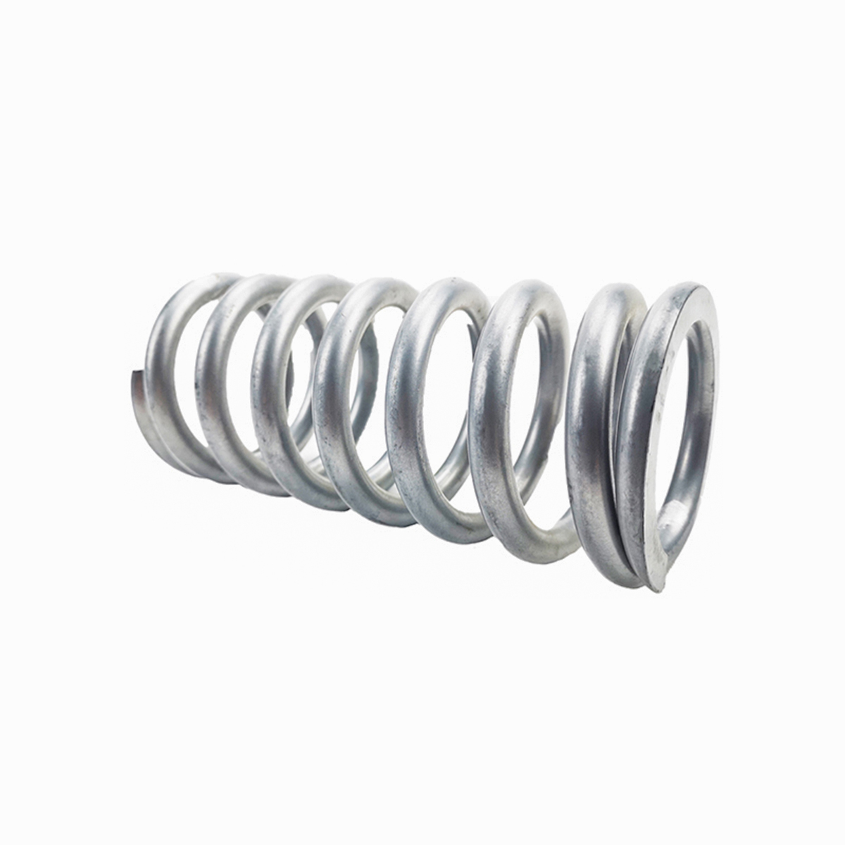
A long, slender compression spring can bow sideways. A buckled spring rubs on its guide and loses force, and the extra bending stress shortens its fatigue life. Shigley’s limit for steel springs on pivoting ends is a free length below 2.63 times the mean coil diameter. For springs with ground ends on flat, parallel seats the limit is about double that [3].
Coil clash is coils hitting each other, usually because the spring is used too close to solid or because surge waves bunch the coils together. Both wear the coils and break up the surface finish, which can start fatigue cracks and corrosion.
Prevention. Keep the slenderness ratio within the limit, or guide the spring over a rod or inside a tube with clearance for the coils to grow. Keep the maximum working deflection to no more than about 87% of the deflection to solid, which gives the 15% fractional overrun to closure Shigley recommends [3].
Surge and resonance in dynamic springs
When a spring is cycled near its own natural frequency, a wave travels along the coils. The coils bunch up and clash, and the stress can rise far above the static calculation. Over-revved engine valve springs are the textbook example [3]. Shigley recommends a natural frequency of at least 15 to 20 times the frequency of the force or motion [3].
This matters for springs on cams, linkages and anything driven by an engine or motor. It also matters for the vibrator springs that support vibrating screens. There, the natural frequency of the machine on its springs is kept well below the running speed for isolation, while the spring’s own surge frequency must stay well above the excitation. For a given wire size, the surge frequency rises as the coil diameter and the number of active coils fall [3]. On an isolation spring the rate is fixed by the isolation requirement, so check the surge frequency at that rate with your spring maker rather than stiffening the spring (see our spring rate guide).
Hook and leg failures in extension and torsion springs
Extension and torsion springs often break at their ends rather than in the body.
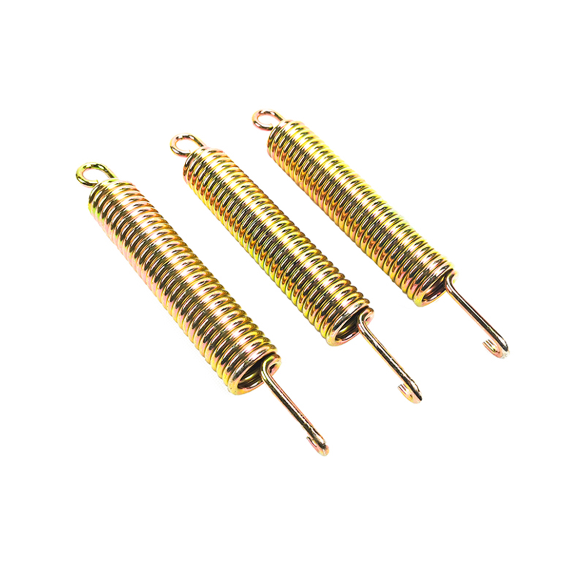
- Extension spring hooks. The highest bending stress is at the bend where the hook turns up from the body. The torsion stress peaks where the hook joins the coils [3]. A tight bend radius raises both. Larger bend radii, a hook formed from a reduced-diameter end coil, or a different end such as an extended hook or a threaded insert reduce the stress. Our guide to extension spring hook types compares the options.
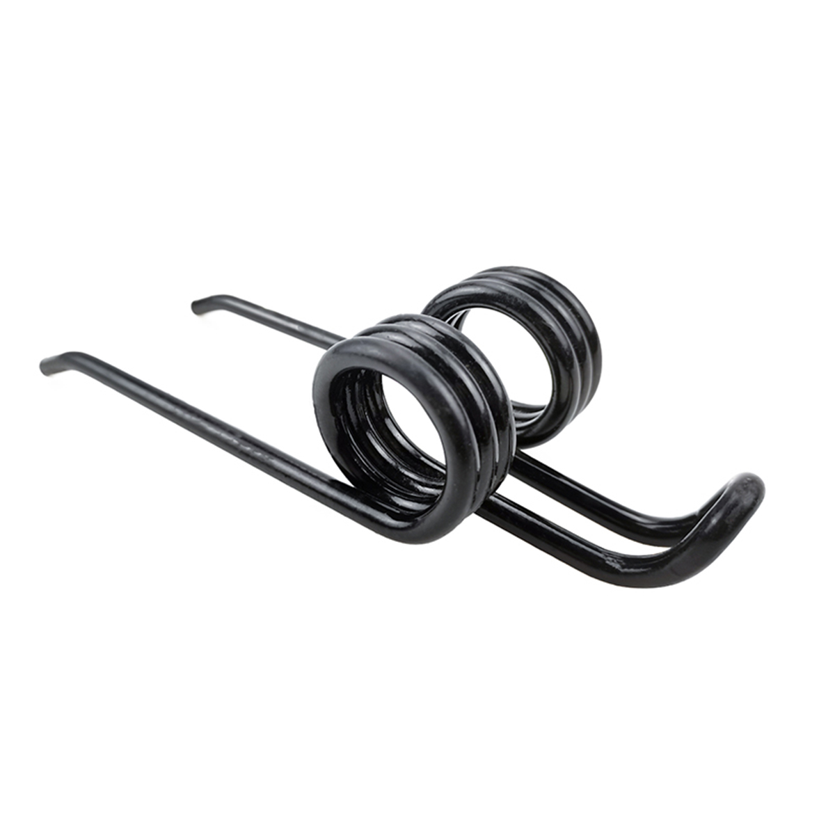
- Torsion spring legs. Legs are loaded in bending, and the stress is highest where the leg leaves the coil body. ASM describes a hard-drawn steel double torsion spring for hay equipment that failed by bending fatigue starting on the inside of the legs where they joined the body. The spring had sprung back past neutral in service and was being cycled in the unwinding direction. The fix was a higher stress-relief temperature to reduce the residual coiling stress [11]. Load torsion springs in the direction that closes the coils. Hardness and finish matter at the leg root too. As an example of a typical specification, a double torsion tine we make is coiled from nominal Ø10 mm 65Mn wire, hardened to 42–47 HRC and finished with a black RAL 9005 polymer coating: the hardness range controls the strength available at the leg root, and the coating keeps field moisture away from it. Our torsion spring guide, double torsion spring guide and spring tines guide explain why.
How to investigate a broken spring
A structured investigation separates the root cause from the symptoms. ASM’s general sequence runs from background information and visual examination through fractography, chemical analysis and metallography to a report [12]. For springs, that becomes:
- Collect the history. Part number, batch, date fitted, hours or cycles in service, load and travel, operating temperature and environment, and what changed recently.
- Keep the evidence. Keep all pieces and some unbroken springs from the same batch. Do not fit the broken ends together, wire-brush them or leave them to rust.
- Measure the springs. Compare free length, diameters and coil count with the drawing, and compare broken springs with unbroken ones. A spring that has shortened has taken a set. Our guide on how to measure a spring explains the method.
- Look at the fracture. Beach marks and a smooth zone point to fatigue; a granular surface with no deformation points to embrittlement; a twisted, fibrous surface with bent coils points to overload. In hardened spring wire an overload break can also run at about 45°, so check for the absence of beach marks and for deformed coils rather than relying on texture alone. Note where the origin is: inner surface, outer surface, a pit, a mark or the hook bend.
- Test the material. Hardness, chemical composition and a metallographic section show whether the wire matches its specification, whether heat treatment was right and whether there is decarburization or inclusions at the origin.
- Check the design. Recalculate the stress at the working and solid lengths, the stress range, the buckling ratio and the natural frequency against the actual service conditions.
- Decide and confirm. Change the design, material, process or installation. Then confirm the fix with a load test and, where life matters, a fatigue test on samples.

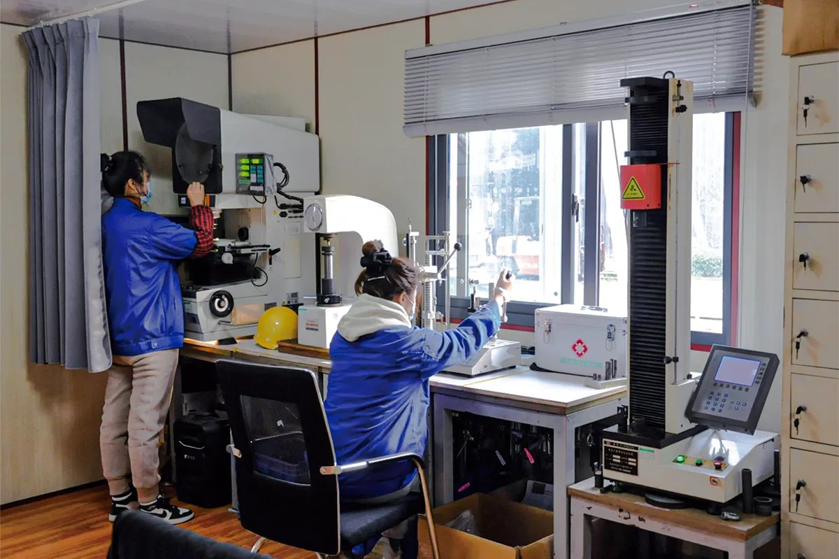
Send the failed parts, photos of the fracture and the service history, and our engineers will review the design and propose a correction. Our in-house laboratory includes spring tension and compression testers, a torsion tester, a spring fatigue tester, Rockwell and micro Vickers hardness testers, a metallographic microscope, a material analyser and a salt spray tester. See our capabilities.
Prevention checklist for your drawing and RFQ
Most spring failures can be designed out before the first part is made. When you specify a spring, include:
| Item | Why it prevents failure |
|---|---|
| Both working loads and lengths (or angles), and the maximum possible travel | Lets the maker check the stress range and the stress at solid |
| Cycle rate and required life | Decides whether fatigue design, shot peening or a fatigue test is needed |
| Operating temperature range | Decides the material and the allowance for relaxation |
| Environment: water, salt, fertiliser, chemicals, cleaning agents | Decides the material and finish |
| Finish, and whether hydrogen relief is required | Prevents corrosion and hydrogen embrittlement |
| Shot peening and presetting, where needed | Raises fatigue strength and resistance to set |
| How the spring is guided and mounted | Prevents buckling, rubbing and coil clash |
| Wire specification and decarburization limit for critical springs | Controls surface quality, a common fatigue origin |
| Any failure history with the current part | Helps the maker go straight to the root cause |
Our compression spring, extension spring and torsion spring specification guides list everything to send for a quote.
Have a spring that keeps failing?
Send us the failed parts, photos of the fracture and how the spring is used. NorenSpring has made custom springs since 2001. We work from drawings, sketches or physical samples, reply with engineering feedback within 24 hours, and have no fixed minimum order quantity for replacement or redesigned springs.
Send your failed spring details See our capabilities
Frequently asked questions
Why do springs break?
Most springs break by fatigue: a crack starts at the surface and grows a little with every load cycle until the wire snaps. The crack usually starts on the inside of the coil, where the stress is highest, or at a defect such as a corrosion pit, a tool mark or a decarburized layer. Fatigue is made worse by a high stress range, corrosion, resonance and a lack of shot peening. Less often, springs break from a single overload or from hydrogen embrittlement after plating.
What causes a spring to lose tension?
A spring loses force when it takes a set, a permanent loss of free length. It happens when the stress exceeds the material’s elastic limit, for example when the spring is compressed to solid, or through relaxation over time, which grows quickly with temperature. Presetting during manufacture, a lower design stress and a material rated for the operating temperature prevent it.
How long should a spring last?
It depends on the stress range, the material, the surface condition and the environment, so there is no single number. A spring designed for infinite life is expected to survive at least 10 million cycles under EN 13906-1 if it is cold coiled [13]. A spring designed for a limited life is expected to fail at a predictable number of cycles. Ask for a fatigue test on samples when life matters.
Can shot peening stop spring fatigue?
It cannot stop fatigue, but it raises fatigue strength substantially. Shot peening puts the wire surface into compression, which slows crack starting and growth. Zimmerli’s tests found about 42% higher maximum stress for valve spring wire after shot blasting [7]. It does not help wire with seams or surface cracks, and its benefit is lost if the spring is later heated too much.
How do I know if a spring failed from fatigue or overload?
Look at the fracture surface. A fatigue fracture has a smooth zone with curved beach marks spreading from one origin, and a smaller rough zone where it finally broke, with little visible deformation. An overload fracture is rough and fibrous all over and usually comes with bent or twisted coils. A brittle, granular break soon after plating with no beach marks suggests hydrogen embrittlement.
About the authors
This guide was prepared by the NorenSpring engineering team, which designs and manufactures custom compression, extension and torsion springs and wire forms in Xuzhou, China. Technical review by Feng Yulin, General Manager and senior structural engineer, who has 15 years of spring R&D experience and more than 30 national patents. NorenSpring holds IATF 16949, ISO 9001, ISO 13485, ISO 14001 and ISO 45001 certifications. More about NorenSpring. Sources and figures were last checked on October 15, 2026.
Sources
The numbers in square brackets in the text refer to this list.
- J. H. Maker, Failures of Springs, ASM Handbook Vol. 11: Failure Analysis and Prevention, ASM International, 2002. Source for the four root-cause groups and the statement that in most cases they result in failure by fatigue. Retrieved 2026-10-15.
- ASM International, Fatigue Fracture of Alloy Steel Valve Springs Because of Pipe, ASM Failure Analysis Case Histories: Processing Errors and Defects. Source for the 45° torsional fatigue fracture with beach marks starting at subsurface inclusions with partial decarburization. Retrieved 2026-10-15.
- R. G. Budynas and J. K. Nisbett, Shigley’s Mechanical Engineering Design, 9th edition, McGraw-Hill, 2011, chapter 10 (Mechanical Springs). Source for the stress distribution and correction factors, set removal and allowable stresses (Table 10-6), the buckling limit, surge and the 15 to 20 times rule, and the stresses in extension spring hooks.
- G. Naumann and H. Spies, Prematurely Broken Valve Spring, ASM Failure Analysis Case Histories: Mechanical and Machine Components. Source for the fatigue origin at a surface defect instead of the usual inner surface, where shot blasting had not produced the intended compressive stress. Retrieved 2026-10-15.
- Sato, Inoue and Ohno, The Effect of Shot-Peening to Decarburized Spring Steel Plate, Proceedings of ICSP-1, 1981. Source for the halving of fatigue life at 0.19 mm decarburization depth in SUP6. Retrieved 2026-10-15.
- K. Dalaei et al., Influence of shot peening on fatigue durability of decarburized spring steels, Proceedings of ICSP-11, 2011 (Chalmers University of Technology and Volvo Powertrain). Source for typical decarburization limits of 0.1 to 0.2 mm, up to 0.5 mm seen in production, and the 45% gain in fatigue limit from shot peening on 51SiCr7. Retrieved 2026-10-15.
- F. P. Zimmerli, How Shot Blasting Increases Fatigue Life, Machine Design, November 1940. Source for the 42% rise in maximum stress, the fatigue ranges in Figure 3, and the lack of improvement on wire with seams. Retrieved 2026-10-15.
- ISO, ISO 9588:2007, Metallic and other inorganic coatings — Post-coating treatments of iron or steel to reduce the risk of hydrogen embrittlement. Retrieved 2026-10-15.
- ASTM International, ASTM B850-98(2022), Standard Guide for Post-Coating Treatments of Steel for Reducing the Risk of Hydrogen Embrittlement. Retrieved 2026-10-15.
- ASTM International, ASTM B849-02(2019), Standard Specification for Pre-Treatments of Iron or Steel for Reducing Risk of Hydrogen Embrittlement, coordinated with ISO 9587. Source for the 1,000 MPa strength level. Retrieved 2026-10-15.
- ASM International, Effect of Spring Unwinding on Fatigue, ASM Failure Analysis Case Histories: Construction, Mining, and Agricultural Equipment, doi:10.31399/asm.fach.conag.c0051294. Source for the double torsion hay tine that failed at the leg root. Retrieved 2026-10-15.
- G. F. Vander Voort, Conducting a Failure Examination, ASM Handbook Vol. 11, 2002. Source for the general sequence of a failure investigation. Retrieved 2026-10-15.
- CEN, EN 13906-1:2013, Cylindrical helical springs made from round wire and bar. Calculation and design. Part 1: Compression springs. Source for the definition of infinite life as at least 10⁷ cycles for cold-coiled springs. Retrieved 2026-10-15.