

In this article
- Key takeaways
- What defines a torsion spring?
- 1. Start with the mounting: arbor, space and leg anchoring
- 2. Specify wind direction and load it the right way
- 3. Define torque at a working angle, not just a rate
- 4. Choose leg shapes and bends that survive fatigue
- 5. Single or double torsion?
- 6. Choose material and finish for the environment
- 7. Set tolerances and inspection that match the risk
- Custom torsion spring RFQ checklist
- What happens after you send the inquiry
- Have a drawing or a sample spring?
- Frequently asked questions
- About the authors
- Sources
To get an accurate quote for a custom torsion spring, tell the manufacturer five things: the free angle between the legs, the torque you need at one or two working angles, the direction of wind, the diameter of the arbor or pin the spring sits on, and the shape and length of each leg. Add the material or operating environment and the quantity, and an engineer can calculate everything else.
Torsion springs go wrong in different ways from compression springs. The coil body is rarely the problem. A left-hand spring ordered as a right-hand one, a leg bent to the wrong angle, or a body that tightens onto its pin will stop an assembly even when wire diameter and coil count are correct. This guide goes through each input in turn and ends with a checklist you can paste into your RFQ. If you also buy coil springs, our compression spring specification guide covers the matching inputs for those.
Key takeaways
- Specify torque at an angle. “800 N·mm at 90° from free” tells the manufacturer what the spring has to do. A rate on its own does not.
- Always state the wind direction. Load the spring so its coils close and its body diameter gets smaller. Loading it the other way raises stress.
- Leave room for wind-up. The inside diameter shrinks and the body gets longer as the spring winds up. A common rule sizes the arbor at about 90% of the smallest ID under load.
- Wire diameter dominates. Torque rate scales with the fourth power of wire diameter, so wire that is 5% thicker gives about 22% more torque.
- Legs carry the risk. Tight bends at the legs concentrate stress. A bend radius of about 1.5 times the wire diameter is a common design target.
What defines a torsion spring?
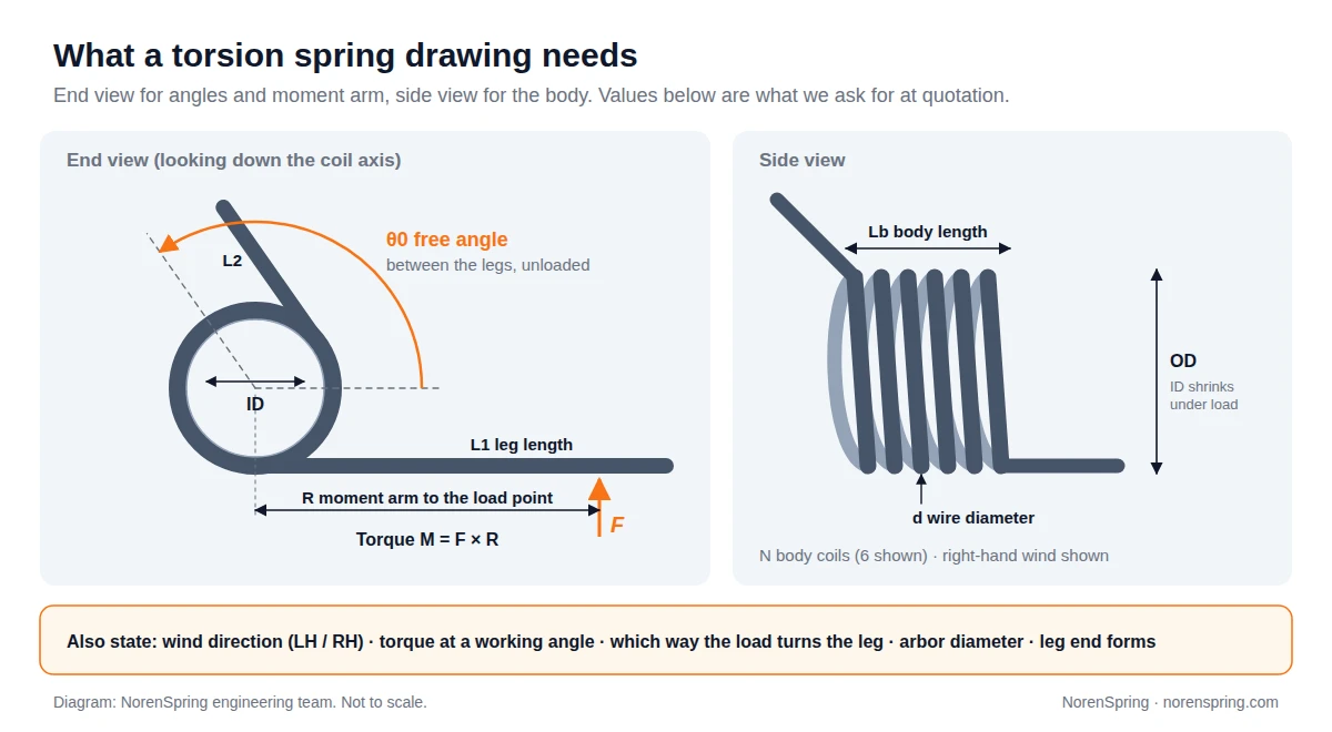
A helical torsion spring stores energy when its legs are rotated around the coil axis. The load goes in through one leg and comes back as torque (moment) around the body. That is why the angles and the lever arm on the drawing matter as much as the coil itself.
| Symbol | Name | Why it matters |
|---|---|---|
| d | Wire diameter | Largest single effect on torque and stress. |
| ID / OD | Inside / outside diameter | ID must clear the arbor after wind-up. OD must clear the housing. Mean diameter D = OD − d. |
| N | Body coils | Sets the torque rate together with d and D. Usually derived by the manufacturer. |
| θ0 | Free angle | Angle between the legs with no load. Every working angle is measured from here. |
| L1, L2 | Leg lengths | Set where the load is applied and how much the legs themselves bend. |
| R | Moment arm | Distance from the coil centre to the load point. Torque M = F × R. |
| M1 / θ1, M2 / θ2 | Working points | The torque you need at the installed and fully rotated positions. |
| LH / RH | Direction of wind | Must match the direction your mechanism turns the leg. |
Our torsion spring product page shows the leg styles we make. The inputs above apply to all of them.
1. Start with the mounting: arbor, space and leg anchoring
Before any torque calculation, describe how the spring is held. Give the diameter of the pin, shaft or arbor it slides over. Give the axial space available for the body. Say how each leg is anchored: in a hole, against a flat face, in a slot, or hooked over a pin.
This matters because a torsion spring changes shape as it works. When it winds up, it gains part of a turn. Its inside diameter gets smaller and its body gets longer. Engineers Edge, drawing on Shigley’s Mechanical Engineering Design, gives the reduced inside diameter as ID × N / (N + θ), with θ in turns, and the loaded body length as d × (N + 1 + θ).
How much clearance does the arbor need?
Size the arbor for the smallest inside diameter the spring will reach, not for the free ID. Lee Spring’s guidance is that “the ideal mandrel size is equal to, or slightly less than, 90% of the inside diameter when the spring is fully deflected.” MW Components gives the same 90% figure. If the arbor is too large, the coils bind on it at full rotation. Friction then rises, torque readings scatter and the wire can wear through.
Leave axial room as well. A spring that winds up against a shoulder or housing wall at each end cannot lengthen freely. The coils then rub against each other and against the housing.
2. Specify wind direction and load it the right way
Every torsion spring is either left-hand or right-hand wound, and the two are not interchangeable. To check a sample, Newcomb Spring’s method is to hold the spring vertically with your thumb pointing up and your fingers wrapped around the body. The hand whose fingers follow the direction of the last coil is the hand of the spring. Right-hand springs wind the same way as a standard right-hand screw thread.
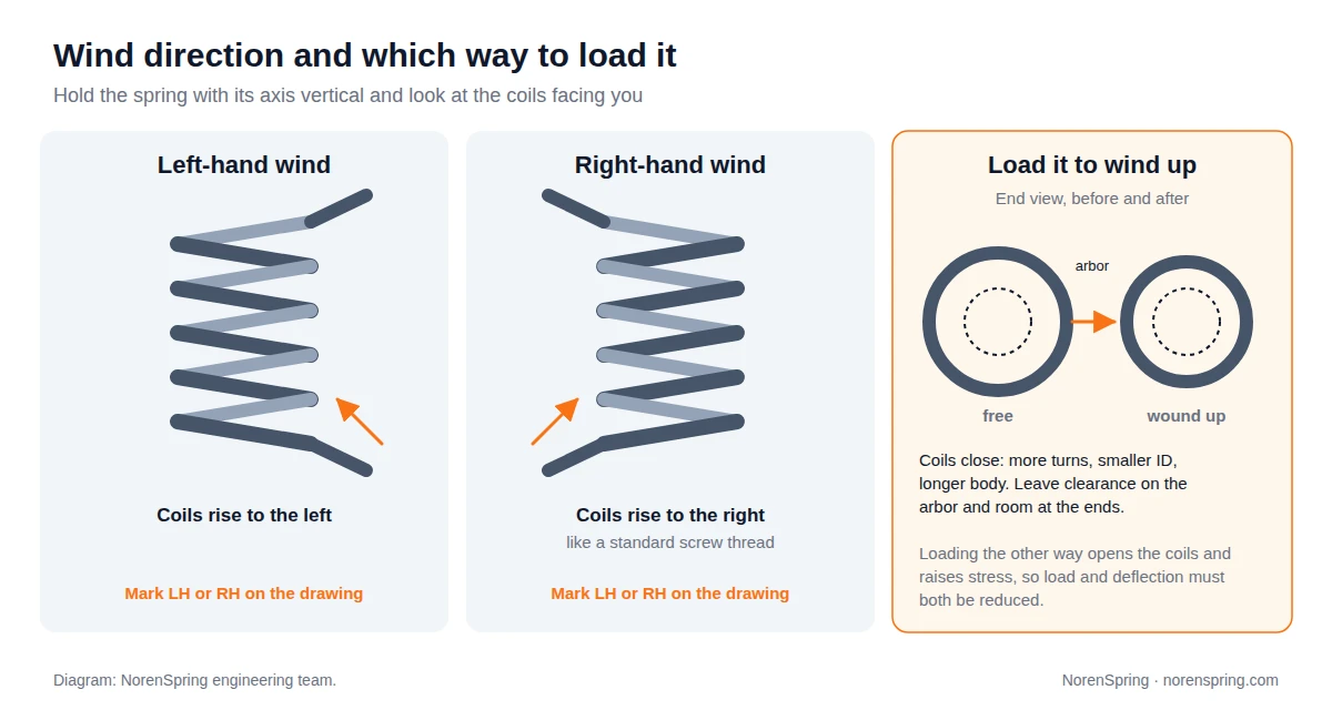
Then check which way your mechanism turns the leg. Lee Spring’s rule is that “a torsion spring should always be loaded in a direction that causes its body diameter to decrease.” Engineers Edge gives the reason: stresses are higher when the load opens the body. If your design has to load the spring the other way, say so on the drawing. The manufacturer then has to lower the allowable load and deflection.
Mark “LH” or “RH” next to the end view. If you send only a sample, also send a photo of it installed. The installed photo shows which leg is fixed and which way the moving leg turns.
3. Define torque at a working angle, not just a rate
The most useful line on a torsion spring drawing is a torque at a stated angle, for example “M1 = 266 N·mm at 30° from free, M2 = 799 N·mm at 90° from free.” It describes the function you are paying for. It also lets the manufacturer adjust coil count and free angle to hold that torque despite normal variation in wire size.
Give the angle as rotation from the free position, or give both the free angle and the installed angle between the legs. Either works, but the drawing must say which. Mixing the two is a common reason why a replacement spring’s legs do not line up with the original’s.
The torque rate comes from wire diameter, mean coil diameter, coil count and the material’s modulus of elasticity. Shigley’s formula, as quoted by Engineers Edge, is k = d⁴E / (10.2 × D × N) torque per turn. The constant rises to 10.8 to allow for friction between the coils and the arbor. Because wire diameter enters to the fourth power, small changes matter. Wire 5% thicker raises the rate by about 22%, and wire 5% thinner cuts it by about 19%. Our spring rate guide compares the rate formulas for compression, extension and torsion springs side by side.
A worked example
Take a music wire spring with d = 2.0 mm, mean diameter D = 16 mm (so ID = 14 mm) and 6 body coils. The legs are short, so their own bending can be ignored. Longer legs, such as 25 to 30 mm on this spring, would lower the rate by several percent. With E = 207 GPa (30 × 10⁶ psi, the value Western Spring lists for ASTM A228 music wire), the formula gives:
- Rate: 207,000 × 2.0⁴ / (10.8 × 16 × 6) ≈ 3,194 N·mm per turn, or about 8.9 N·mm per degree.
- Torque: about 266 N·mm at 30° and 799 N·mm at 90° from free.
- Inside diameter at 90° (0.25 turn): about 13.4 mm, whether you apply the relation to the inside diameter (14 × 6 / 6.25 ≈ 13.44 mm) or to the mean diameter and subtract the wire (16 × 6 / 6.25 − 2 ≈ 13.36 mm). Using the 90% rule, the arbor should be no larger than about 12 mm.
- Body length: grows from 14.0 mm free to about 14.5 mm at 90°.
- Bending stress at 90°: the spring index is C = D/d = 8, so the curvature factor Ki = (4C² − C − 1) / (4C(C − 1)) ≈ 1.10. The stress is Ki × 32M / (πd³) ≈ 1,120 MPa. An engineer then compares this with the allowable bending stress for that wire size and material.
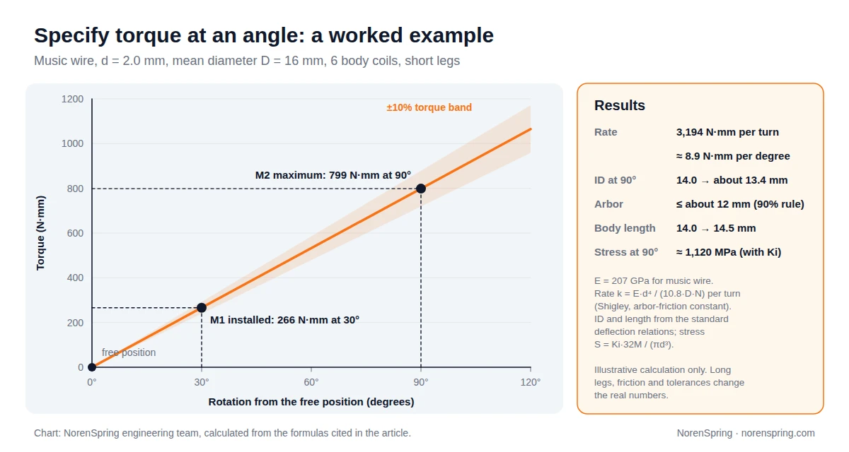
This is an illustrative calculation, not a design. Long legs add flexibility, friction adds hysteresis and tolerances widen the result. Those effects are why you should specify the torque you need and let the manufacturer set the coil count.
4. Choose leg shapes and bends that survive fatigue
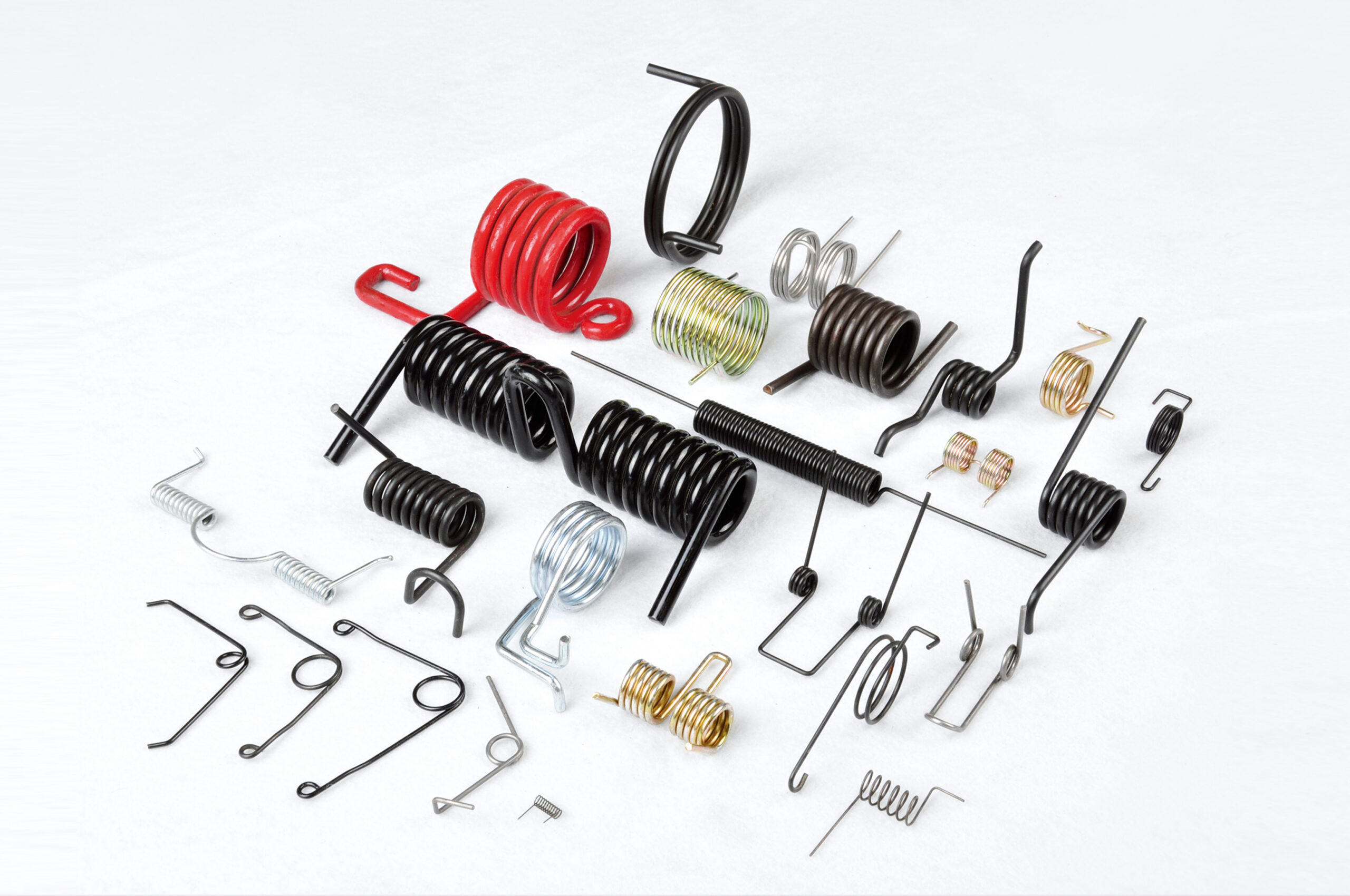
Legs are where most torsion spring problems start. Straight tangential legs are simplest to make and to measure. Hooks, offsets, hinge ends and legs bent back across the body are all possible. Each one adds a bend, and each bend concentrates stress.
Newcomb Spring notes that “breakage (fracture) will sometimes occur at the bends on torsion springs or wire forms when the radius is too tight,” and that “it is best, however, to design the radius to be 1.5 times the diameter of the material.” If your part needs a sharper bend to fit, show the radius on the drawing so it can be checked before tooling is made.
For each leg, give:
- The length from the coil centre, or from the body, to the load point. The moment arm R depends on it.
- The end form, such as straight, hooked, bent at 90° or with a formed tip, with its dimensions.
- Which leg is fixed and which one moves.
- Any tolerance that matters for fit, such as the position of a hook relative to a hole.
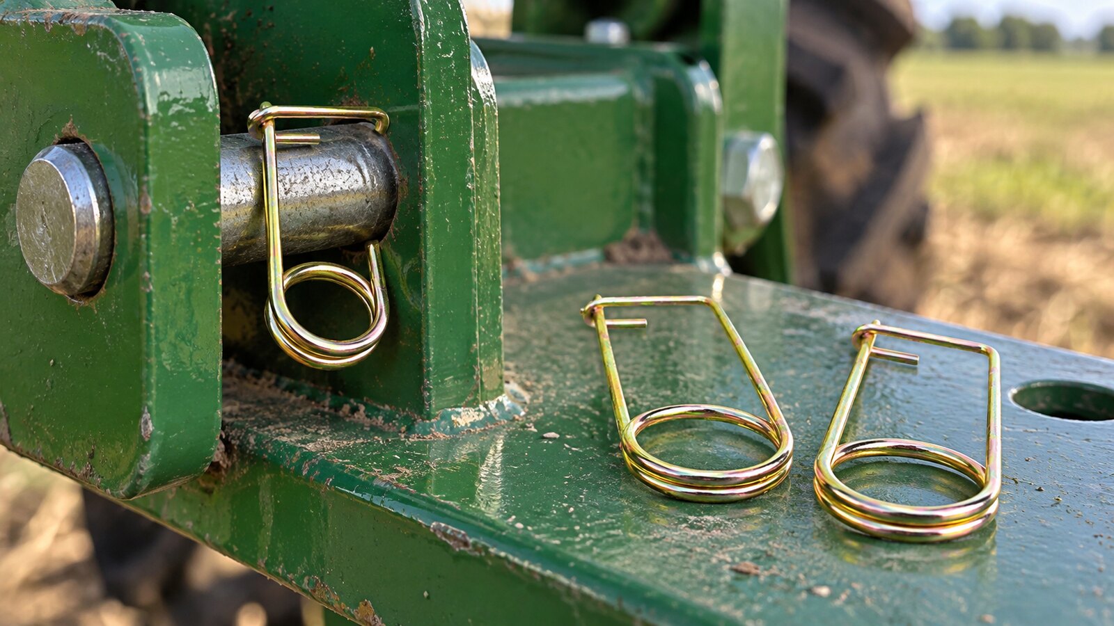
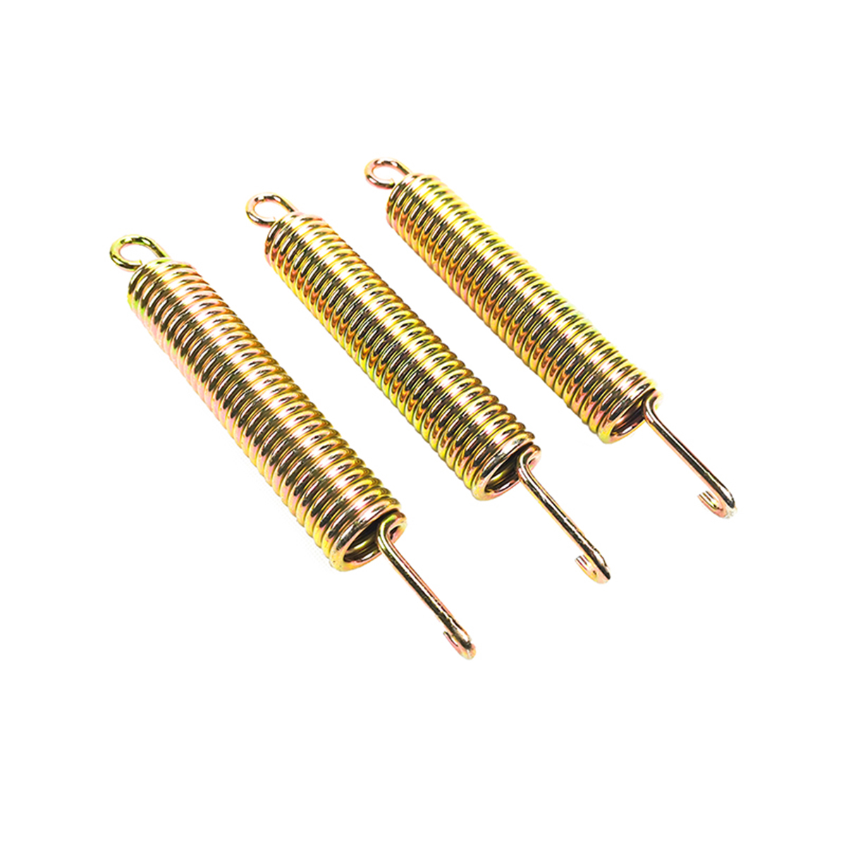
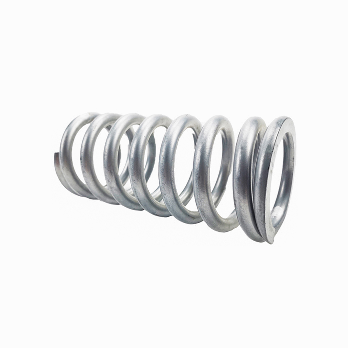
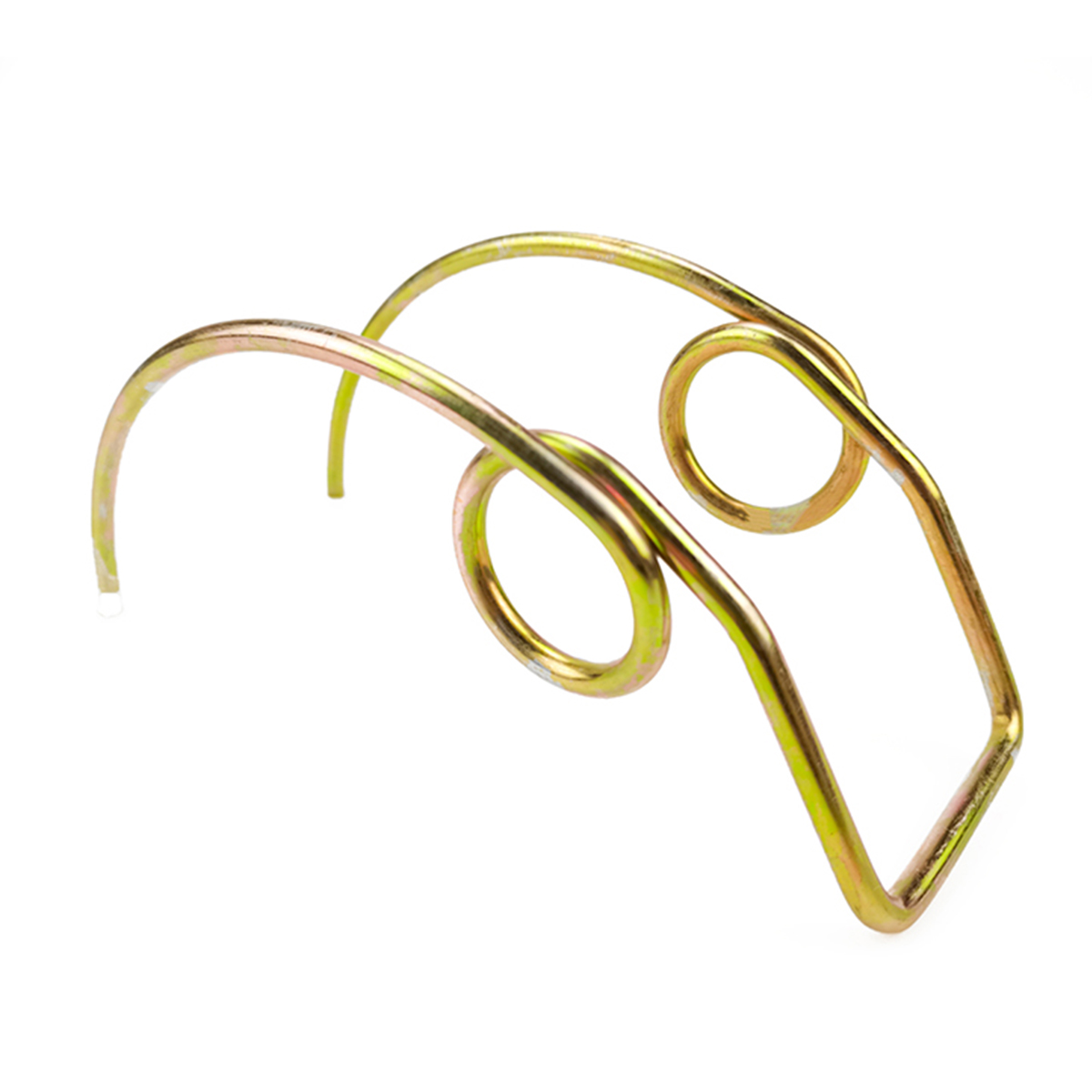
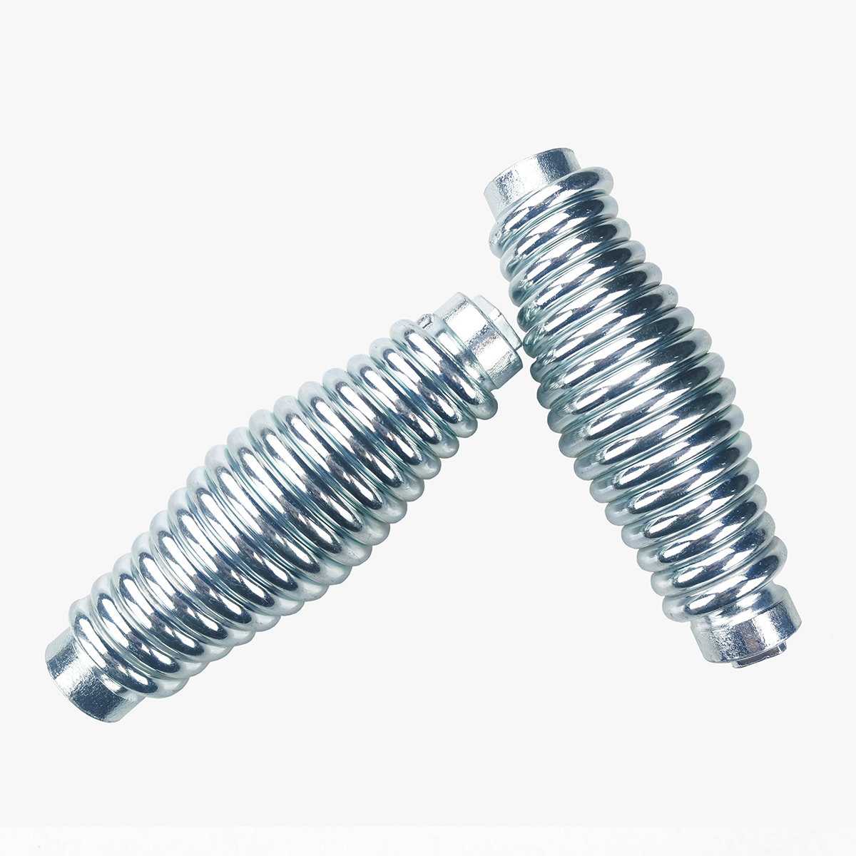
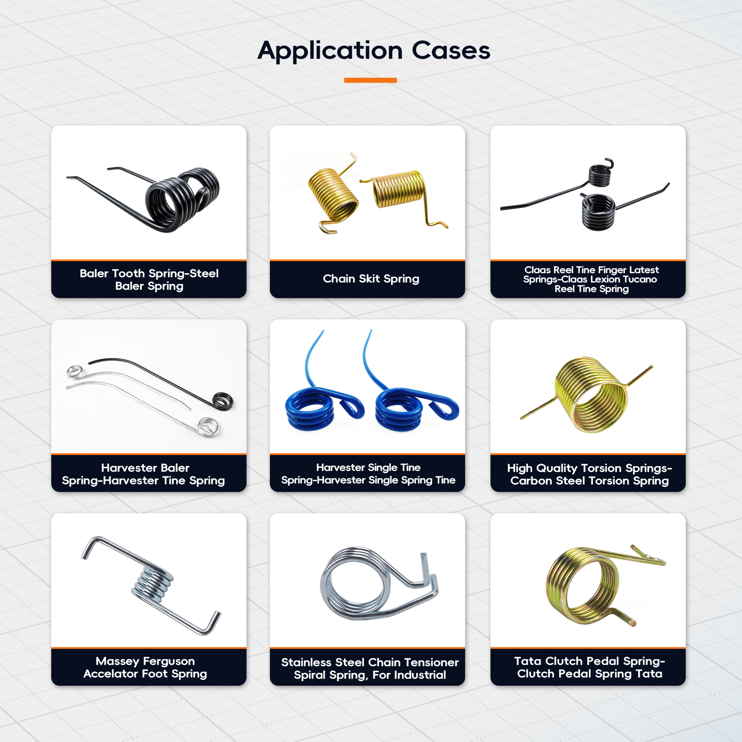
The parts above show how varied leg geometry can be on springs whose bodies look much alike. You can see the full set, with materials and wire ranges, on our torsion spring application cases page.
5. Single or double torsion?
A double torsion spring has two coil bodies wound in opposite directions and joined by a length of wire. Century Spring calls this middle section the hairpin. Lee Spring describes double torsion springs as “one set of coils coiled right hand and one set of coils coiled left hand,” with “the total torque being the sum of the two.” They give a balanced load across a wide part, which is why baler pickup tines and some seat and lid mechanisms use them.
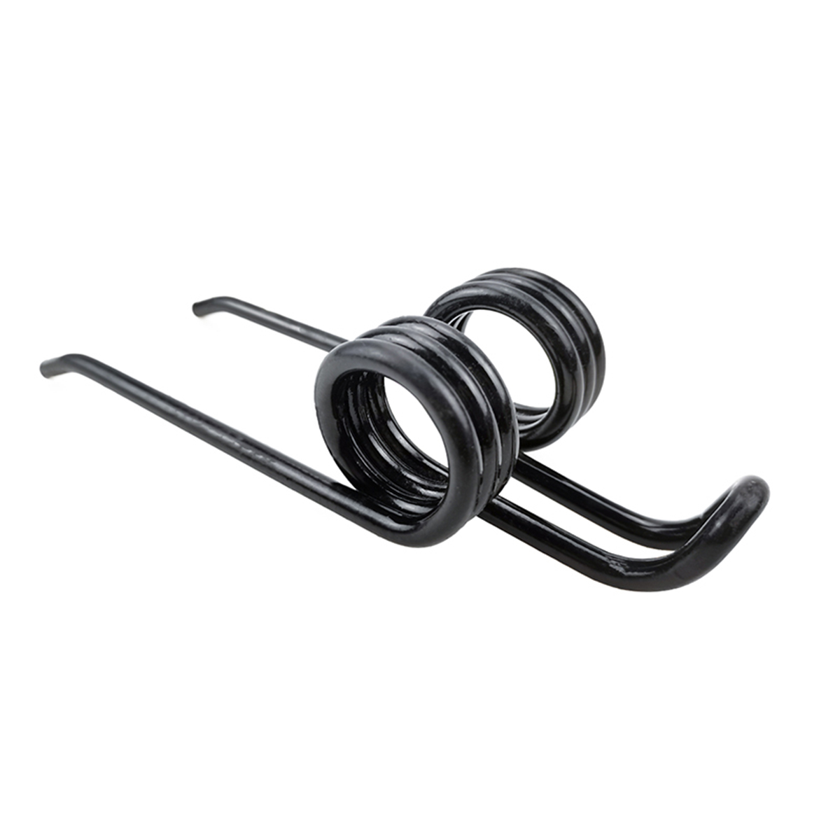
When you specify a double torsion spring, give the torque for the whole spring and say whether it is measured at the hairpin or at the legs. Give the width across the two bodies, the hairpin shape and the position of the legs. Both halves have to match, so tolerances on the coil count and leg angle of each half matter more than on a single spring. Tines that combine a double torsion body with long formed legs overlap with wire forms. Our agricultural machinery spring solutions page shows where they are used. For baler, rake and tedder tines specifically, our spring tines guide covers what to measure on a worn sample.
6. Choose material and finish for the environment
Pick the material for the conditions the spring works in: temperature, moisture, chemicals and cleanliness. Then let the manufacturer confirm the wire size and stress. Our spring wire material guide compares the common grades and their equivalents.
Material also changes torque. Torque rate is proportional to the modulus of elasticity E. Spring makers list about 30 × 10⁶ psi for music wire and oil-tempered wire, and about 28 × 10⁶ psi for 302/304 stainless (DR Templeman, Optimum Spring). So a stainless spring with the same geometry gives roughly 7% less torque than a carbon steel one. If you switch to stainless for corrosion resistance, the wire size or coil count usually has to change to hold the torque.
The wires we work with include carbon spring wire, music wire, oil-tempered wire, silicon-chrome and alloy spring steels, stainless steel 304 and 316, beryllium copper, phosphor bronze, and nickel and titanium alloy spring wire.
For finishes, state what the spring has to survive and whether its colour has to match an existing part. Zinc plating, black oxide, phosphate, powder coating and passivation for stainless are common choices. Electroplating can let hydrogen into high-strength spring steel. ASTM B850, which is technically equivalent to ISO 9588, covers heat treatments applied after plating to reduce the risk of hydrogen embrittlement. ASTM notes that the treatment “does not guarantee complete freedom” from hydrogen effects, so agree the finish and any baking step before production.
7. Set tolerances and inspection that match the risk
Tolerance only the characteristics that affect your assembly. For most torsion springs those are torque at a working angle, free angle, and the ID that fits the arbor.
For comparison, Lee Spring’s published tolerances for its stock torsion springs are ±10% on torque, ±10° on free leg position for 3 to 10 coils, and ±15° for 11 to 20 coils. MW Components describes typical tolerances as about ±10% in torque and ±5% in diameter. In Germany, DIN 2194 sets requirements and testing for cold-coiled cylindrical helical torsion springs up to 17 mm wire diameter. For calculation and design, the European standard is EN 13906-3:2014. Tighter tolerances are possible, but they usually cost more to hold, so ask for them only where they matter.
Say how torque should be measured: at which angle, from which leg, and with or without an arbor. Two springs can read differently on the same tester if one is measured on a pin and the other is not.
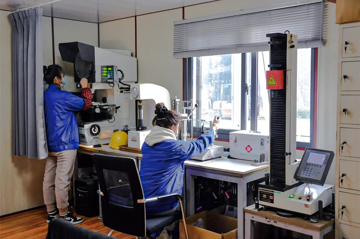
At NorenSpring, torque and angle are checked on JISC PRO-T series torsion testers, and dimensions on vision measuring systems. We also have hardness testers, a metallographic microscope and spring fatigue testers for projects whose control plan calls for them. Documentation is agreed at project setup and can include inspection reports, material certificates, dimensional records and traceability.
Custom torsion spring RFQ checklist
Copy this table into your inquiry and fill in what you know. Rows 1 to 5 are the minimum for an accurate quote. If you do not know row 6, we can derive it from the torque and space you give us.
| # | Item | Example |
|---|---|---|
| 1 | Free angle between legs | 180° |
| 2 | Torque at working angle(s) | 266 N·mm at 30°, 799 N·mm at 90° from free |
| 3 | Direction of wind and load direction | RH, load closes the coils |
| 4 | Leg lengths and end forms, fixed vs moving leg | L1 12 mm straight, L2 15 mm with 90° hook |
| 5 | Arbor diameter and axial space | Pin 11.5 mm, 16 mm between shoulders |
| 6 | Wire diameter, OD or ID, body coils | d 2.0 mm, ID 14.0 mm, coils: derive from torque |
| 7 | Material or environment | Music wire, indoor, dry |
| 8 | Surface finish | Zinc plated and baked / black oxide / none |
| 9 | Duty or cycle life | Hinge return, about 20 cycles per day |
| 10 | Quantity, timing and records | 200 samples, then 50k/year; material cert + torque report |
No drawing? A sample, a photo of it installed, and the torque you need at the working position are enough to start.
What happens after you send the inquiry
Our 28+ engineers review each inquiry and send engineering feedback or a quotation within 24 hours. Each project then goes through the same stages. First comes a requirement review of torque, angles, mounting, environment and your drawing or sample. Next, prototype tooling and samples are made for dimensional, torque and fit approval. Samples usually take 7 to 15 working days, and production 15 to 30 working days. The exact lead time is confirmed at quotation, because it depends on material, tooling, quantity and approvals. CNC coiling and forming then control body diameter, coil count and leg geometry. Stress relief and the agreed finish follow, then inspection against the control plan, and finally packing with export documentation. There is no fixed minimum order quantity. Our capabilities page explains each stage in more detail.
Have a drawing or a sample spring?
Send the drawing, CAD file (DWG, DXF, STEP or PDF) or photos you already have, with the torque and angles you know. An engineer will confirm the missing values, check wind direction, arbor clearance and leg stress, and quote from there.
Upload a drawing View torsion springs
Frequently asked questions
What is the minimum information needed to quote a torsion spring?
The free angle, one torque at a stated angle, the direction of wind, the leg lengths and end forms, and the arbor size. Add the wire diameter, ID or OD and coil count if you have them, plus the quantity. With those, an engineer can check stress and arbor clearance before quoting.
Can a torsion spring work in both directions?
It can, but it should not be designed that way if you can avoid it. A torsion spring should be loaded in the direction that closes the coils. If the mechanism also turns it the other way, stress is higher in that direction, so the allowable load and deflection must be reduced. State both directions on the drawing so the manufacturer can check them.
Why don’t the legs of my replacement spring line up with the original?
There are three common causes. The free angle may have been measured on an installed spring rather than a free one. The wind direction may be reversed. Or the free angle tolerance may be wider than your assembly allows. Measuring the original’s free angle on the bench and marking LH or RH avoids the first two causes. Asking for a tighter angle tolerance where it matters fixes the third.
Why did my torsion spring break at the leg?
Fractures at the leg usually start at a tight bend, where stress is concentrated. Loading the spring in the unwinding direction, or rotating it beyond its design angle, makes this worse. A bend radius of about 1.5 times the wire diameter and a check of the maximum working angle are the usual first steps. Our wire forms design guide shows how quickly bending stress rises as the radius gets tighter.
What if I only have a sample and no drawing?
That is a common starting point. Send the sample, or photos with measurements, and describe where it is installed and which leg moves. We can measure the geometry, test torque against angle on a torsion tester and propose a drawing for your approval.
About the authors
This guide was prepared by the NorenSpring engineering team, which designs and manufactures custom compression, extension and torsion springs and wire forms in Xuzhou, China. Technical review by Feng Yulin, General Manager and senior structural engineer, who has 15 years of spring R&D experience and more than 30 national patents. NorenSpring holds IATF 16949, ISO 9001, ISO 13485, ISO 14001 and ISO 45001 certifications. More about NorenSpring.
Sources
- Engineers Edge, Torsion Spring Coil Stress, Torsion Spring Coil Deflection and Torsion Spring Design, citing R. G. Budynas and J. K. Nisbett, Shigley’s Mechanical Engineering Design, 9th ed. Source for the stress, curvature factor, rate, inside diameter and body length relations and the loading direction rule. Retrieved 2026-09-28.
- Lee Spring, Learn About Torsion Springs and Engineering Notes and Tolerances. Source for the loading direction, 90% mandrel guidance, double torsion definition and stock tolerances. Retrieved 2026-09-28.
- MW Components, How to Select a Torsion Spring. Source for mandrel sizing and typical tolerances. Retrieved 2026-09-28.
- Newcomb Spring, Helical Spring Wind Direction and Torsion Spring Wire Forming Radii. Source for identifying the hand and the 1.5 × d bend radius guidance. Retrieved 2026-09-28.
- Century Spring, Double Torsion Springs. Source for the hairpin description. Retrieved 2026-09-28.
- BSI, EN 13906-3:2014, Cylindrical helical springs made from round wire and bar. Calculation and design. Torsion springs; SIS, DIN 2194, Cold coiled cylindrical helical torsion springs: requirements and testing. Retrieved 2026-09-28.
- ASTM International, ASTM B850-98(2022), Standard Guide for Post-Coating Treatments of Steel for Reducing the Risk of Hydrogen Embrittlement. Retrieved 2026-09-28.
- Western Spring, Music Wire; DR Templeman, About Spring Materials; Optimum Spring, 302/304 Stainless Steel Spring Wire. Source for modulus of elasticity values. Retrieved 2026-09-28.