

In this article
- What are wire forms?
- Common wire form types, materials and sizes
- How are wire forms made?
- Design rules that keep a wire form manufacturable
- How to dimension and tolerance a wire form drawing
- How do surface finishes affect fit?
- How are wire forms inspected?
- Example: R-pin clips that did not fit consistently
- Wire form RFQ checklist
- Frequently asked questions
- About the authors
- References
Wire forms are parts made by bending spring wire into a fixed two- or three-dimensional shape, such as a clip, R-pin, hook, retaining ring or tine. Unlike a coil spring, a wire form works mainly through its bend angles and leg lengths. It locates, holds or springs back against a mating part, so the drawing has to fix that shape precisely.
That changes what a good specification looks like. With a compression spring you give loads at lengths and let the manufacturer pick the coils. With a wire form, almost every size on the drawing is a shape decision you have made, and a few of those decisions decide whether the part is easy to make or will crack, drift out of tolerance or jam in assembly. This guide covers the design rules, how to dimension and tolerance the drawing, how finishes change the fit, how parts are inspected, and what to send for a quote. It completes our series with the compression spring, extension spring and torsion spring specification guides.
Key takeaways
- Bend radius drives stress. At an inside radius of half the wire diameter, the peak bending stress at the bend is about 1.63 times the nominal value. At one wire diameter it is 1.33 times.
- Angles are the hardest size to hold. Spring wire springs back after every bend. Put tight tolerances only on the angles and positions that affect fit.
- Pick one datum. Measure every size from it. Sizes chained from bend to bend stack up their errors.
- Do not lean on ISO 2768. Its scope is machined and sheet-metal parts, not bent wire. Agree the general tolerance for your part at quotation.
- Finish is part of the size. Plating adds thickness to every surface. Electroplated spring steel needs a hydrogen-relief bake, which we apply to all our zinc-plated springs.
What are wire forms?
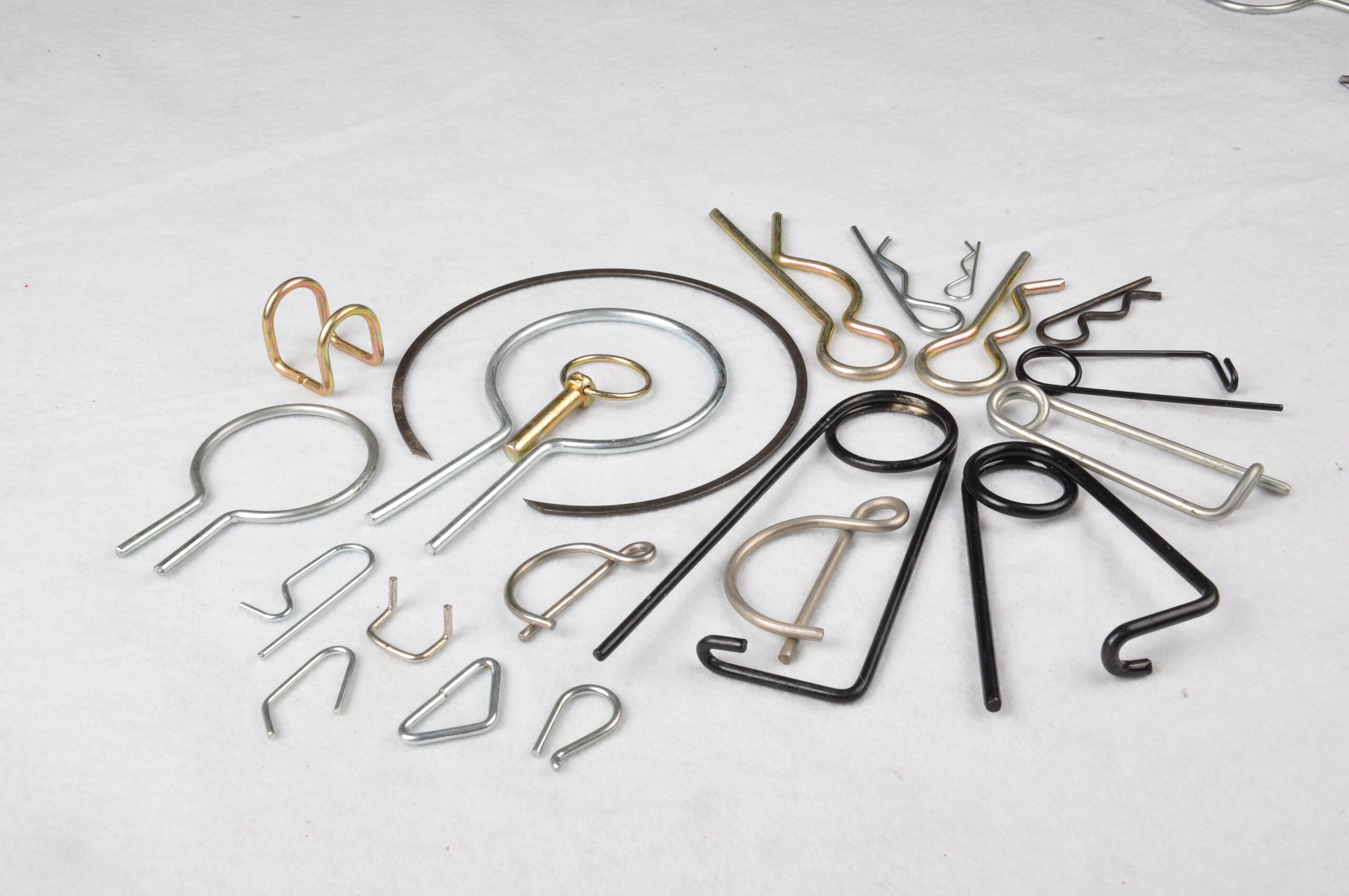
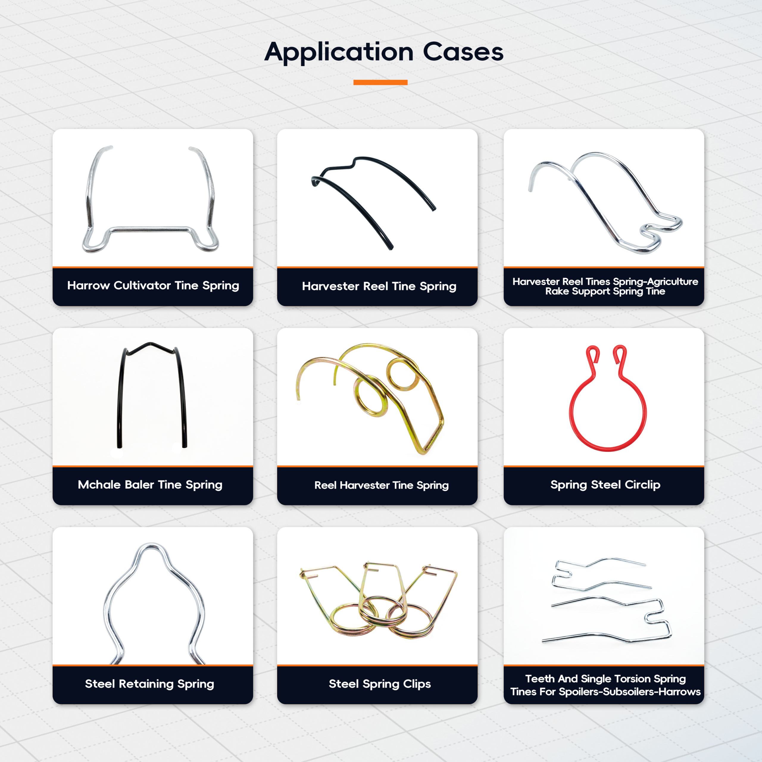
A wire form is any part made by bending wire rather than coiling it into a helix, although many include a coil or two where they need to flex. The family is wide. It includes R-pins and hitch pins, circlips and retaining rings, spring clips, hooks, handles, spring tines for farm machinery, seat wires and electrical contact springs.
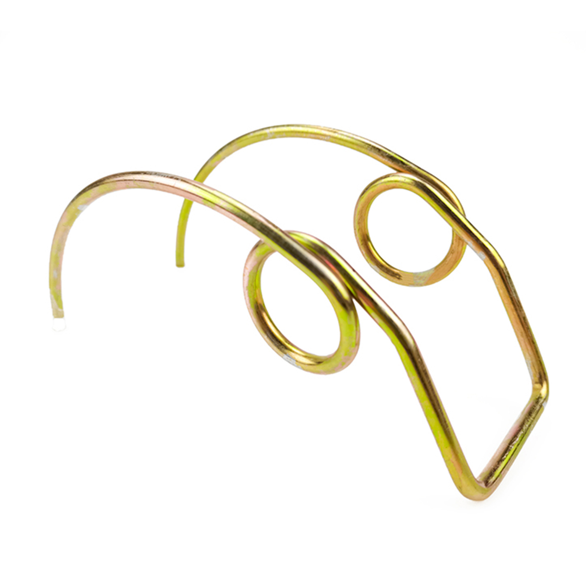
Most wire forms do one of four jobs:
- Retain. Circlips, R-pins and retaining springs stop a pin, shaft or cover from coming loose.
- Clamp or grip. Spring clips hold a part against another with a set force.
- Locate or guide. Bent wire positions a component, carries a cable or acts as a handle.
- Flex and return. Tines and contact springs bend in service and must come back to shape every time.
The job decides which sizes matter. A retaining clip lives or dies by its opening and grip. A tine lives or dies by its bend radii, because it flexes millions of times. We supply wire forms to automotive, electronics and agricultural machinery customers, including seat springs and electronic contact springs. The wire forms case page shows nine of our parts with their materials and finishes.
Common wire form types, materials and sizes
The table lists the wire form types we make most often, with the material, wire diameter and usual finish our production team gives for each, and the size that usually decides whether the part works. Wire sizes outside these ranges are reviewed against the drawing.
| Wire form | Typical job | Material | Wire diameter | Usual finish | Size that decides fit |
|---|---|---|---|---|---|
| Spring steel circlip | Retains a part in a shaft groove | 65Mn or SK5 | 0.5–3 mm | Black oxide | Free inside diameter against the groove |
| Steel spring clip | Clips parts together, often with a coil | Carbon or stainless steel | 0.5–3 mm | Zinc or nickel plating | Opening after finish |
| Steel retaining spring | Holds a component in place | Carbon steel | 1–5 mm | Zinc plating | Contact points from the datum |
| R-pin clip | Secures a clevis or hitch pin | Carbon spring steel | Per drawing | White or yellow zinc | Gap and position of the hump |
| Harvester reel tine | Lifts crop toward the cutter bar | 50CrVA | 5–9 mm | Powder coating | Mounting eye and bend radii |
| Single torsion spring tine | Levels soil on harrows and subsoilers | 50CrVA or SWOSC-V | 5–12 mm | Phosphate or powder coating | Tine angle and coil position |
50CrVA and 65Mn are Chinese GB spring steels, SWOSC-V is a Japanese JIS valve-quality spring wire and SK5 is a Japanese high-carbon steel. Our spring wire material guide lists their ASTM and EN equivalents.
How are wire forms made?
Wire forms are made by CNC wire bending: a CNC wire forming machine straightens the wire, bends it in two or three dimensions, adds any coils and cuts it off in one cycle. The part then goes through stress relief, finishing and inspection. Two of those later steps change the size of the part, so the drawing has to allow for them.
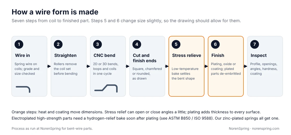
- Wire in. Coils are checked for grade and diameter before use.
- Straighten. Rollers remove the set the wire took on the coil. Any residual curve shows up as a bowed leg.
- CNC bend. The machine feeds the wire and bends it to programmed angles. Simple 2D parts and many 3D parts need no dedicated tooling. Some shapes need a fixture or a second operation.
- Cut and finish ends. Ends are sheared. Ends that a person handles, or that enter a hole, can be chamfered or rounded.
- Stress relieve. A low-temperature bake relieves the stress left by bending, which helps the shape stay put and improves fatigue life. It can move angles slightly, which is why first samples are measured after this step and not before.
- Finish. Zinc, nickel, black oxide, phosphate, powder coating or passivation for stainless steel.
- Inspect. Profile, openings, angles, hardness and coating are checked against the agreed control plan.
Our manufacturing videos show the route from wire to inspected part in our plant.
Design rules that keep a wire form manufacturable
Four choices decide most of the cost and risk in a wire form: the bend radius, the space between bends, the wire ends and the way the drawing is dimensioned. Getting these right before the first quote saves a round of samples.
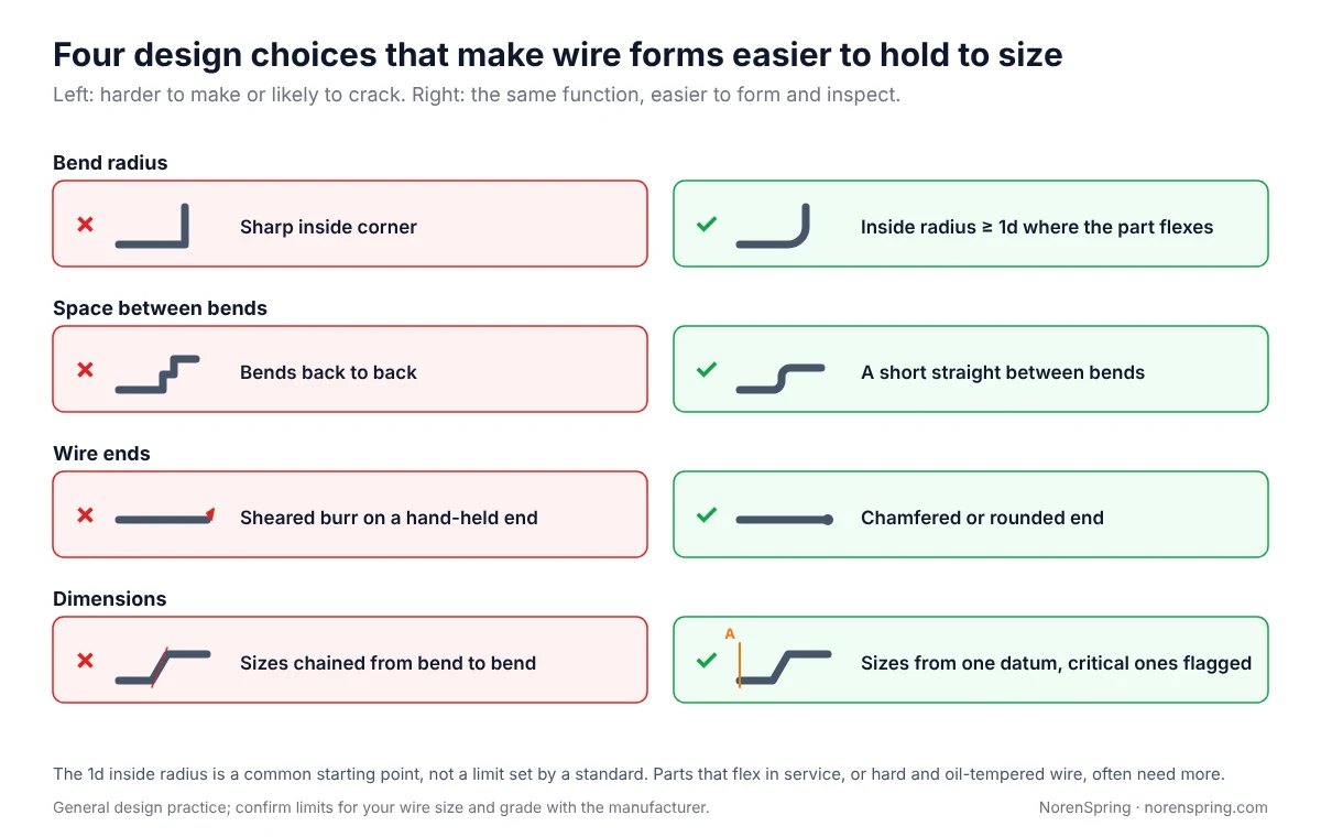
Give every bend an inside radius
Bending puts the highest stress on the inside fibre of the bend, and the tighter the bend, the higher that peak. Wahl’s curved-beam factor, given in Shigley’s Mechanical Engineering Design for spring hooks, puts numbers on it. We calculated it for common inside radii:
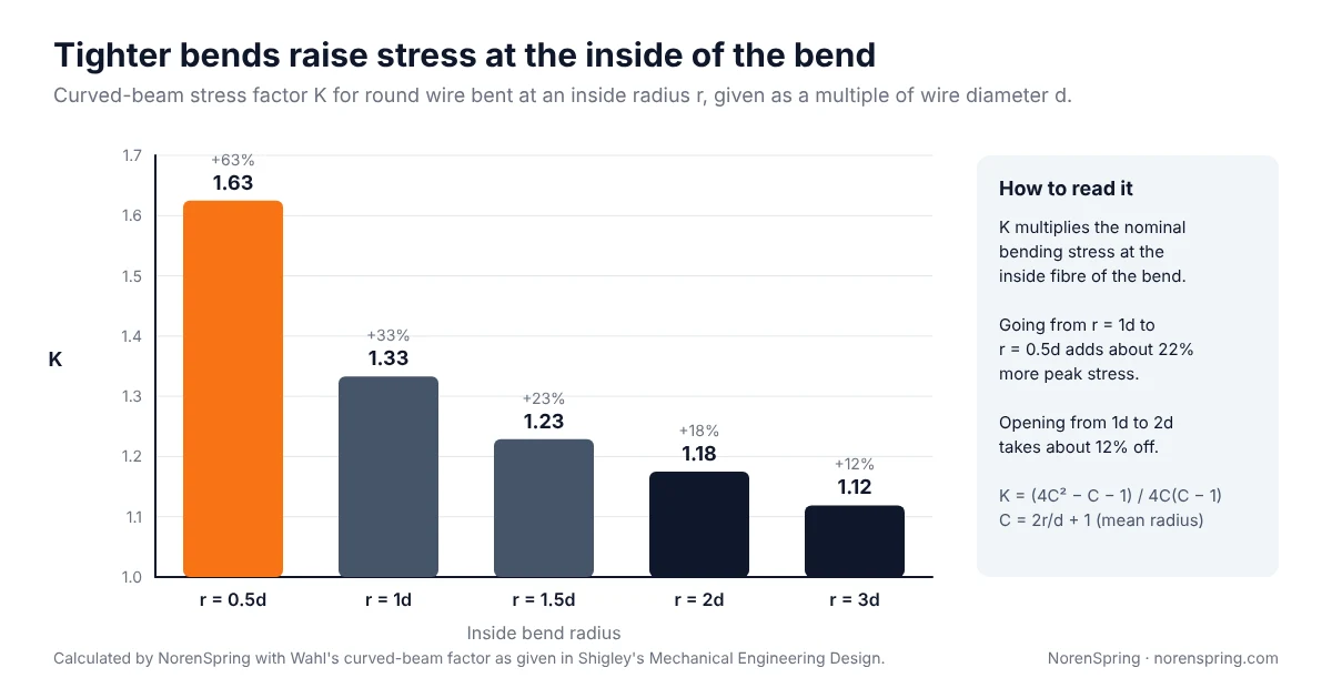
Tightening a bend from one wire diameter to half a wire diameter adds about 22% to the peak stress, with no change in the load. Opening it from one to two wire diameters takes about 12% off. An inside radius equal to the wire diameter is a common starting point. Parts that flex in service, such as tines and clips that are removed often, usually deserve more. Hard-drawn and oil-tempered wire is generally less forgiving of tight bends than annealed wire.
If a sharp corner is truly needed, for example to clear a mating part, say why on the drawing so the engineer can look for another way to get the clearance.
Leave a straight between bends
The bending head needs a short straight length to grip between one bend and the next. Bends placed back to back may need a special tool or a second operation. Bends also interact: the springback from the second bend pulls on the first. If two bends must be close, ask the manufacturer for the minimum straight for your wire size before you fix the design.
Decide what the ends must do
A sheared end has a small burr and a slightly angled face. That is fine inside an assembly. On a handle, a clip that people push by hand, or a pin that has to enter a hole, ask for a chamfered or rounded end and say which ends need it.
Keep the shape symmetric where it can be
Double tines, U-forms and clips with two legs sit square only if both sides match. Symmetric shapes are also easier to fixture and gauge. If the part must be asymmetric, mark which side is which so it cannot be assembled the wrong way round.
How to dimension and tolerance a wire form drawing
Dimension a wire form from one datum, give tight tolerances only to the sizes that affect fit or function, and mark everything else as reference or general tolerance. Angles are the size most affected by springback, so they deserve the most thought.
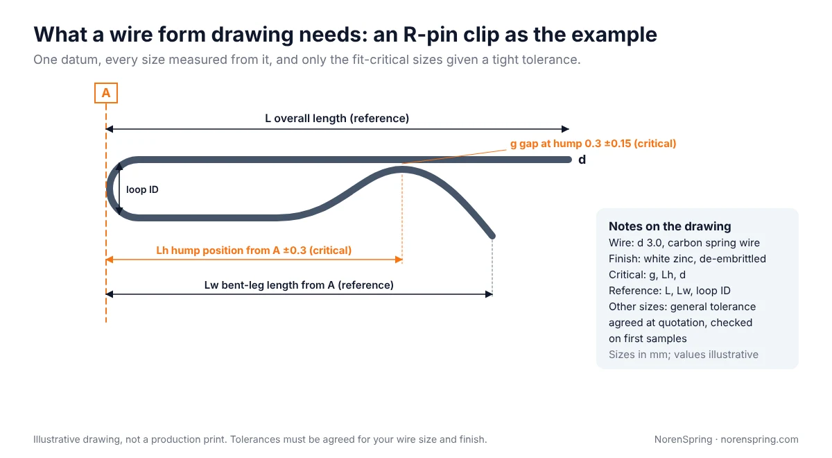
Choose one datum and measure from it
Pick a feature the part is located by in use, such as a loop, an eye or a straight leg, and call it datum A. Measure every position from it. When sizes are chained from bend to bend, each tolerance adds to the next, and the far end of the part can drift well beyond what any single size allows.
Say whether a size is to the centreline, inside or outside
A leg length can be measured to the wire centreline, to the inside of a bend or to the outside. The three differ by half a wire diameter or more. Pick one convention, note it on the drawing and use it everywhere.
Tolerance the angles that matter, and only those
Spring wire springs back after every bend, by an amount that varies with wire strength, diameter and bend radius from coil to coil. CNC machines compensate by overbending, and an angle can be held tightly where it counts. Each tight angle costs set-up time and inspection, though. Give a tight angle tolerance where the angle sets the fit, such as a clip opening or a leg that must enter a slot. Let the other angles follow a looser general tolerance.
Do not rely on ISO 2768 for bent wire
Many drawings carry a title-block note such as “general tolerances ISO 2768-m”. The scope of ISO 2768-1 covers parts made by metal removal or formed from sheet metal. Bent round wire is outside that scope. The medium class would also hold an angle with a leg up to 10 mm to ±1°, which can be tighter than a small wire form needs. Agree the general tolerance for your part at quotation, and confirm it on first samples.
Mark critical sizes clearly
Flag the sizes that matter with a symbol or a note, such as “critical” or “CC”. This tells the manufacturer what to measure on every sample and what to put in the control plan. Everything else can be checked on first articles and then by fixture.
How do surface finishes affect fit?
A finish changes the size of the part, and on high-strength spring steel it also changes how the part should be processed. Choose the finish with the fit in mind. For a wider comparison of plating, coatings and their corrosion life, see our guide to spring finishes and coatings.
| Finish | Look | Effect on size and processing |
|---|---|---|
| Zinc plating (white, blue or yellow) | Bright silver or yellow | Adds a thin coat to every surface; parts need a hydrogen-relief bake after plating |
| Nickel plating | Bright silver | Adds coating thickness; same hydrogen risk as zinc |
| Black oxide | Black | Negligible change in size; light corrosion protection, usually oiled |
| Phosphate | Dark grey | Thin conversion coat; often oiled or painted over |
| Powder coating or paint | Black, red, blue and other colours | Thickest coat; can fill tight gaps and clip openings |
| Passivation | Bright stainless | For stainless steel; removes free iron, almost no change in size |
Two points catch buyers out. First, the coating goes on both faces of a clip opening and on both legs of an R-pin, so a thick coat closes a gap from both sides. Set critical openings as “after finish” and the manufacturer will form them to allow for it.
Second, electroplating can drive hydrogen into hardened spring steel. The steel can then crack under load days later. A bake soon after plating drives the hydrogen out. ASTM B850 and ISO 9588 describe these post-coating treatments. All our zinc-plated springs are de-embrittled after plating, at temperatures set by the applicable national standard.
For parts that must resist corrosion without plating, stainless 304 or 316 wire is the alternative. It costs more, and its lower strength may call for a thicker wire. The spring wire material guide compares the options.
How are wire forms inspected?
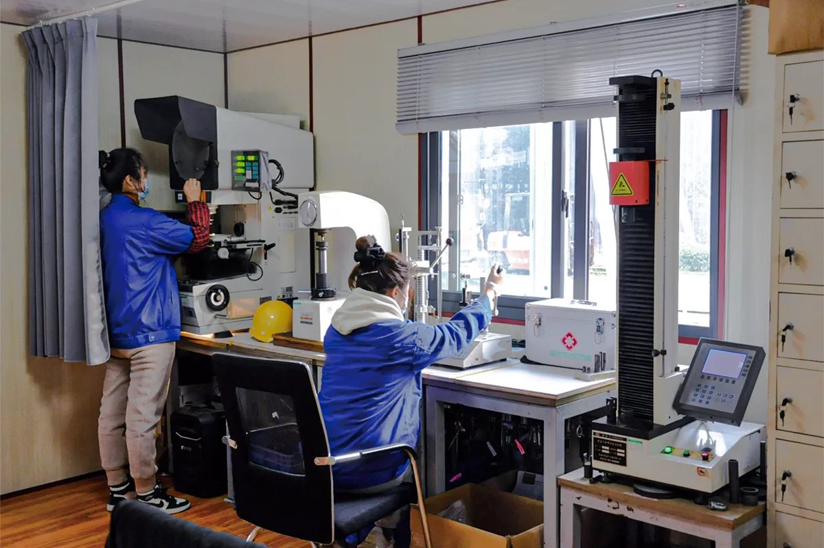
Wire forms are measured mostly by their profile: angles, positions, openings and flatness. Our inspection room checks wire forms on video measuring systems, from the OGP SmartScope ZIP and VMS series, and on Keyence IM-8000 series image measuring systems. These compare the part outline against the drawing without touching it.

Other checks depend on the part:
- Fixtures and go/no-go gauges for fast in-process checks of critical openings and positions in high-volume runs.
- Rockwell hardness testers (Mitutoyo HR-530 and HR-150A) to confirm heat treatment on spring steel.
- Salt spray tester (Q-Fog CCT1100) for corrosion tests on coated parts when the drawing or control plan calls for one.
- Material analyzer (Thermo Scientific Niton XL2) to confirm the wire grade, for example SUS304 against SUS316.
First samples are measured in full and shared for fit and application approval before production. Samples typically take 7 to 15 working days and production 15 to 30 working days. The exact lead time is confirmed at quotation, because it depends on material, tooling, quantity and approvals.
Example: R-pin clips that did not fit consistently
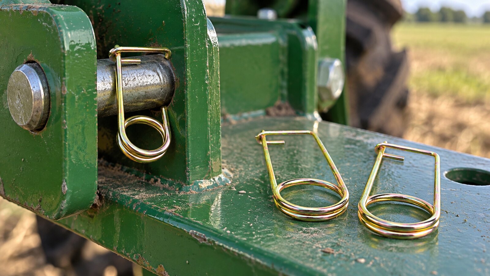
A buyer in Thailand found that white-zinc R-pin clips from a previous supplier varied in size, so some would not fit during assembly. We controlled the opening through the CNC forming parameters, the wire diameter and the zinc plating quality together, and the clips are now in stable batch production. The full project is on our wire forms case page.
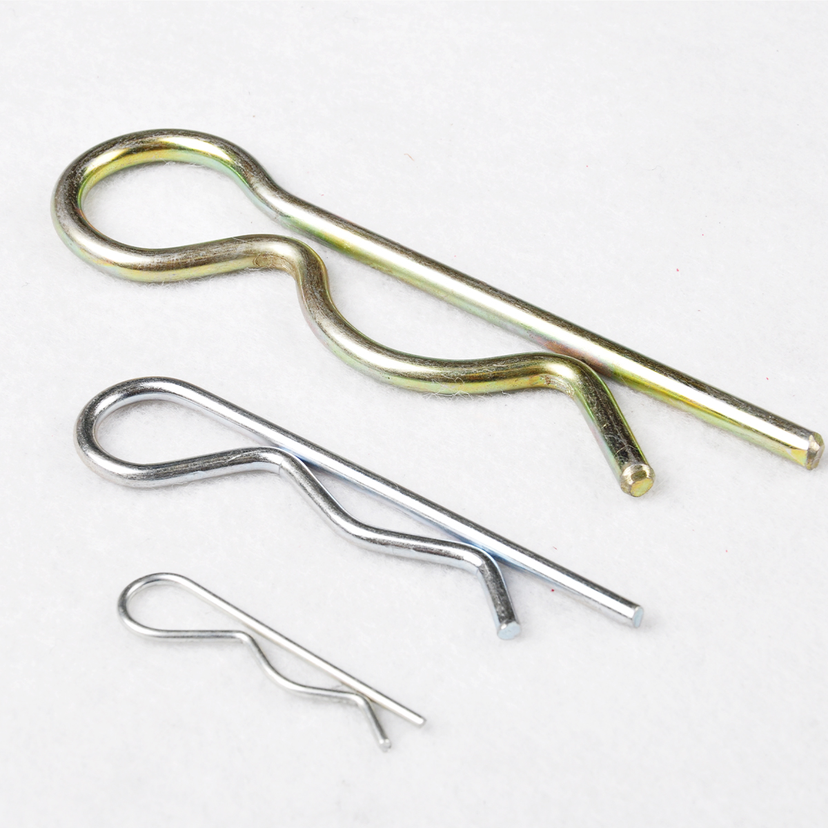
The lesson applies to any clip: the opening is the critical size, and it depends on wire diameter, forming and coating at once. State it “after finish” on the drawing, give it a tolerance, and leave the overall length as a reference size, as in Figure 4.
Wire form RFQ checklist
Send these items with your inquiry for custom wire forms. A drawing or sample covers most of the list, and our engineers will ask about anything missing.
| Item | What to send | Example |
|---|---|---|
| Drawing or sample | DWG, DXF, STEP, PDF or a photo with a scale, or the part itself | STEP file of the clip |
| Wire | Material and diameter, or the environment if you are unsure | 65Mn, 2.0 mm |
| Shape | All bends, legs, loops and coils, from one datum | Datum A at the loop |
| Critical sizes | The sizes that set fit or function, with tolerances | Opening 4.0 ±0.2 after finish |
| Function | What the part must do: hold, grip, flex, carry load | Grips a 10 mm pin, removed weekly |
| Finish | Plating, coating or passivation; colour if it matters | White zinc |
| Environment | Temperature, outdoor exposure, chemicals | Outdoor, field use |
| Quantity | Sample quantity and annual volume | 200 samples, 50,000 a year |
| Documents | Inspection report, material certificate, PPAP if needed | Material cert with each batch |
There is no fixed minimum order. Small batches for replacement parts and high-volume production can both be quoted. Send your drawing or sample through the contact page and our engineers will reply within 24 hours. To see the full range of bent-wire parts we make, visit our wire forms product page.
Frequently asked questions
What is the difference between a wire form and a spring?
A spring stores energy mainly in coils: compression, extension and torsion springs are all helical. A wire form gets its function from its bent shape, through angles, legs and loops. Many parts are both, such as a clip with a torsion coil. These are usually specified like wire forms, with the coil described as one feature of the shape. Our torsion spring guide covers the coil part in detail.
Can you copy a wire form from an old sample?
Yes. Most replacement wire forms start from a sample. We measure the profile on a video measuring system, check the wire grade and hardness, and send a drawing back for your approval before making samples. Tell us which sizes matter in use, because a worn sample may no longer show the original opening or angle. Farm-machinery tines are a common case, and the spring tines guide shows what to measure on them.
What wire diameters can you form?
Our spring range as a whole covers wire from 0.1 mm to 80 mm. The wire forms we make most often use 0.5 to 12 mm wire, as the table above shows. The workable size for a new wire form depends on the shape, the number of bends and the material, so each drawing is reviewed before quoting.
Do wire forms need tooling?
Many do not. CNC wire forming machines can make most 2D and many 3D shapes from a program. Parts with very tight bends, closed loops at awkward angles or high volumes may use a dedicated tool or fixture, which is agreed at quotation.
Why did my wire form crack at a bend?
Cracks at a bend usually come from a radius that is too tight for the wire, a nick or tool mark on the inside of the bend, or hydrogen embrittlement after plating. Check the inside radius first. Figure 3 shows how quickly stress rises below one wire diameter. If the crack appeared days after plating with little load, ask whether the parts were baked after plating.
About the authors
This guide was prepared by the NorenSpring engineering team, which designs and manufactures custom compression, extension and torsion springs and wire forms in Xuzhou, China. Technical review by Feng Yulin, General Manager and senior structural engineer, who has 15 years of spring R&D experience and more than 30 national patents. NorenSpring holds IATF 16949, ISO 9001, ISO 13485, ISO 14001 and ISO 45001 certifications. More about NorenSpring.
The stress factors in Figure 3 were calculated by our team. Wire, finish and lead-time figures come from our production records. The R-pin drawing in Figure 4 is illustrative, not a production print.
References
- Budynas and Nisbett, Shigley’s Mechanical Engineering Design, McGraw-Hill, chapter 10, Mechanical Springs, section on extension springs (bending stress factor for hooks). Source of the curved-beam stress factor for bent wire used in Figure 3.
- ISO, ISO 2768-1:1989, General tolerances, Part 1: Tolerances for linear and angular dimensions. Scope and angular tolerance classes. Retrieved 2026-10-09.
- ASTM International, B850, Standard Guide for Post-Coating Treatments of Steel for Reducing the Risk of Hydrogen Embrittlement. Retrieved 2026-10-09.
- ISO, ISO 9588:2007, Metallic and other inorganic coatings: Post-coating treatments of iron or steel to reduce the risk of hydrogen embrittlement. Retrieved 2026-10-09.