

In this article
- Key takeaways
- What is spring rate?
- Spring rate calculator
- Spring rate formula: how to calculate compression spring rate
- Extension spring rate and initial tension
- Torsion spring rate
- Springs in series, in parallel, and progressive springs
- Spring rate testing: how to measure spring rate on a tester
- Why a measured rate differs from the formula
- How to put spring rate on a drawing
- Spring rate checklist for your RFQ
- Frequently asked questions
- About the authors
- Sources
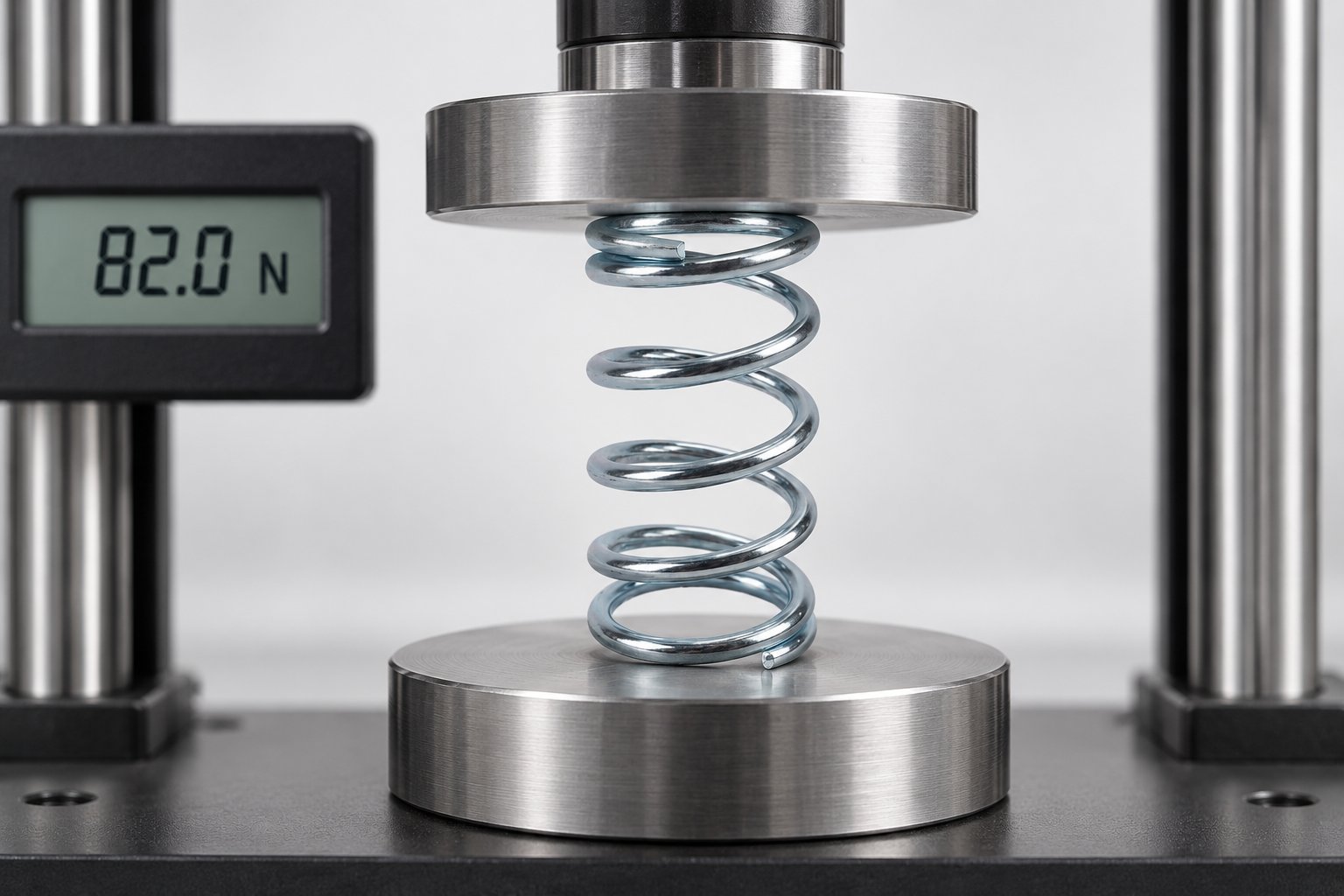
Cover image: an AI-generated illustration of a compression spring on a load tester, not a photograph of our laboratory.
Spring rate is the force needed to deflect a spring by one unit of length. It is written as k and measured in N/mm or lbf/in. For a compression or extension spring, k = ΔF / Δx: the change in force divided by the change in length. For a torsion spring, the rate is torque per degree of rotation, in N·mm/°.
You can calculate spring rate from four inputs: wire diameter, mean coil diameter, the number of active coils and the material’s shear modulus. You can also measure it on a tester by reading the force at two lengths. This guide covers both methods for compression, extension and torsion springs. It explains why a measured rate rarely matches the formula exactly and how to state rate on a drawing so the parts you receive behave the way you designed them. A free spring rate calculator is included below.
Key takeaways
- Rate is a slope, not a force. k = (F2 − F1) / (L1 − L2). Read it from two points in the middle of the travel, never from zero.
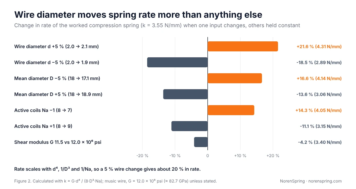
- Wire diameter dominates. Rate scales with d⁴. A wire 5% thicker raises the rate by about 22%. A coil diameter 5% larger lowers it by about 14%.
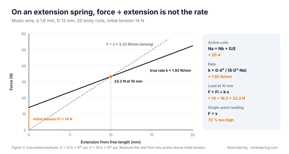
- Extension springs need initial tension in the maths. Force = initial tension + k × extension. Dividing force by extension overstated the rate by 73% in our example.
- Specify forces at lengths. Spring tolerance standards such as EN 15800 grade the force at a test length, and a rate alone does not fix where the force line sits.
What is spring rate?
Spring rate, also called the spring constant or stiffness, is how much force a spring adds for each unit it is compressed, stretched or twisted. A spring with a rate of 3.55 N/mm needs about 35.5 N more force to compress another 10 mm. In US units, the same spring is about 20.3 lbf/in. To convert, 1 N/mm equals 5.71 lbf/in, and 1 lbf/in equals 0.175 N/mm.
“Spring rate” and “spring constant” mean the same thing. Physics courses write Hooke’s law as F = k·x and call k the spring constant. Spring makers and engineering drawings usually say spring rate. For torsion springs, the equivalent is torque rate.
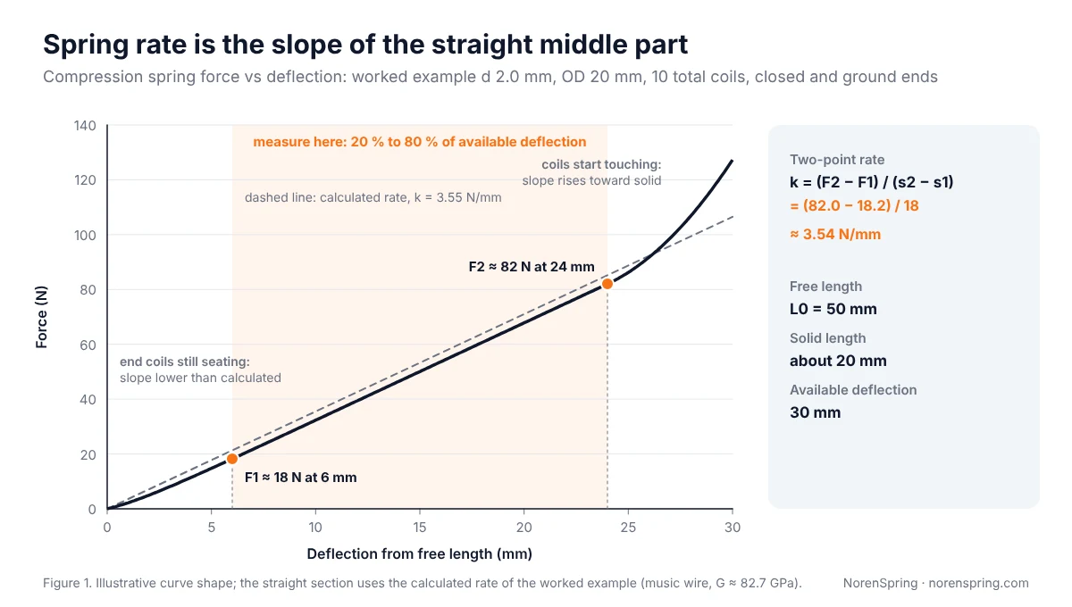
A helical spring has a constant rate only over part of its travel. Over the first part, the end coils are still seating against the plates, so the force rises more slowly than the formula predicts. Near solid length, coils start to touch each other, active coils drop out and the rate climbs. Engineers Edge, citing standard spring design practice, advises measuring rate between 20% and 80% of the available deflection and designing critical loads within that central 60% (Engineers Edge, Helical Compression Spring Design, retrieved 2026-10-07).
Spring rate calculator
The first calculator works out the rate of a compression spring from its dimensions, using the spring rate formula explained in the next section. The second works out the rate from two force readings, which suits any tester result. Both are meant for early design checks and for comparing samples. Confirm final values with a load test.
Compression spring rate calculator
Formula k = G·d⁴ / (8·D³·Na), with D = OD − d and Na = Nt minus the inactive end coils. Pitch angle and end-coil transition are ignored. Results are estimates, not a substitute for testing.
Spring rate from two test points
Spring rate formula: how to calculate compression spring rate
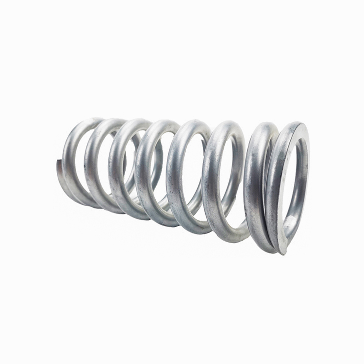
The rate of a round-wire helical compression spring is:
k = G · d⁴ / (8 · D³ · Na)
| Symbol | Meaning | Note |
|---|---|---|
| k | Spring rate | N/mm when G is in N/mm² (MPa) and lengths in mm |
| G | Shear modulus of the wire | A material property. See the table below. |
| d | Wire diameter | Measure it with a micrometer. A caliper is too coarse for small wire. |
| D | Mean coil diameter | D = OD − d, or ID + d |
| Na | Active coils | Total coils minus the inactive end coils |
The formula is the standard one in Shigley's Mechanical Engineering Design (chapter 10, Mechanical Springs) and in the European design standard EN 13906-1 for cold and hot coiled compression springs (BSI, EN 13906-1). It ignores the small effect of pitch angle, which is fine for normal designs.
Active coils depend on the end type
Only coils that are free to deflect add to the deflection. End coils that sit against the plates do not.
| End type | Active coils Na |
|---|---|
| Open (plain) ends | Nt |
| Open ends, ground | Nt − 1 |
| Closed (squared) ends | Nt − 2 |
| Closed and ground ends | Nt − 2 |
These are the usual design values from Shigley. On a real spring, the transition from the closed end coil to the first active coil is gradual, so the effective count can differ by a fraction of a coil. Half a coil makes a difference of about 6 to 7% on an eight-coil spring. That is one reason calculated and measured rates differ.
Shear modulus of common spring materials
| Material | Standard | G (10⁶ psi) | G (approx. GPa) |
|---|---|---|---|
| Music wire | ASTM A228 | 12.0 (up to 0.100 in), 11.75 above | 82.7 / 81.0 |
| Hard drawn carbon steel | ASTM A227 | 11.5 | 79.3 |
| Oil tempered carbon steel | ASTM A229 | 11.5 | 79.3 |
| Chrome vanadium | ASTM A231 | 11.5 | 79.3 |
| Chrome silicon, oil tempered | ASTM A401 | 11.5 | 79.3 |
| Stainless steel 302/304, 316 | ASTM A313 | 10.0 | 68.9 |
| 17-7 PH stainless | AMS 5678 | 11.0 | 75.8 |
| Phosphor bronze | ASTM B159 | 6.25 | 43.1 |
| Beryllium copper | ASTM B197 | 7.0 | 48.3 |
Values from the Engineers Edge spring material table (retrieved 2026-10-07), converted at 1 × 10⁶ psi = 6.895 GPa. Stainless steel has a shear modulus about 13% lower than carbon and alloy spring steels, and about 17% lower than fine music wire, so a stainless spring with the same geometry has that much less rate. If you switch an existing design to stainless for corrosion, the wire or coil count has to change to keep the same force. Our spring wire material guide gives the Chinese, Japanese, European and US equivalents for each grade.
Worked example
A music wire compression spring has d = 2.0 mm, OD = 20 mm and 10 total coils with closed and ground ends.
- Mean diameter: D = 20 − 2 = 18 mm
- Active coils: Na = 10 − 2 = 8
- G = 12.0 × 10⁶ psi ≈ 82,737 N/mm²
- k = 82,737 × 2.0⁴ / (8 × 18³ × 8) = 1,323,792 / 373,248 ≈ 3.55 N/mm (about 20.3 lbf/in)
With a free length of 50 mm and a solid length of about 20 mm, the spring has 30 mm of available deflection. The useful working range by the 20% to 80% rule is 6 mm to 24 mm of deflection, or about 21 N to 85 N on the calculated line.
Why small dimension changes matter so much
Because wire diameter enters the formula to the fourth power and coil diameter to the third, small differences in either move the rate a lot. In the example above, with the mean diameter held constant, wire that is 5% thicker raises the rate by 21.6%. A coil diameter 5% smaller raises it by 16.6%. One coil fewer raises it by 14.3%.
This is why a replacement spring that "looks the same" can feel noticeably stiffer or softer. It also means a drawing that fixes d, OD, coil count and free length all at once leaves the manufacturer no room to correct the rate. Our compression spring specification guide explains which dimensions to fix and which to leave free, and our custom compression springs page shows the sizes and materials we make. Wave springs follow different rules, with the rate rising with the fourth power of the waves per turn, and our custom wave spring guide shows how each dimension moves it.
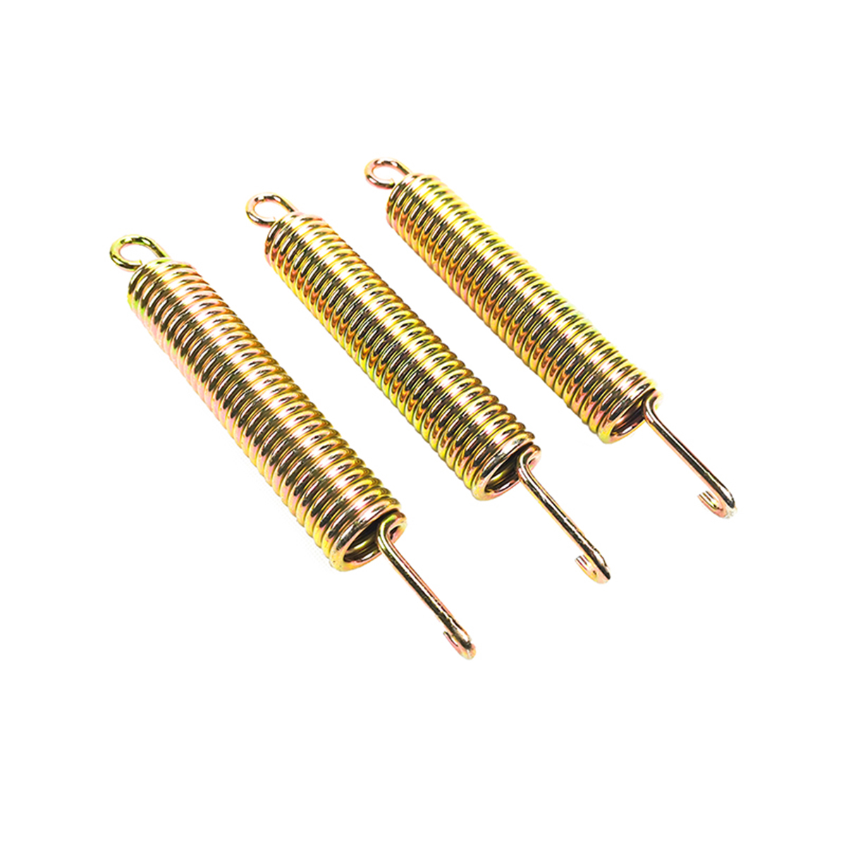
Extension spring rate and initial tension
An extension spring uses the same rate formula, with two differences. The active coil count is the body coil count plus a small allowance for the hooks, Na = Nb + G/E in Shigley's treatment. More importantly, a close-wound extension spring is made with initial tension. It does not start to stretch until the pull exceeds that tension.
The load on an extension spring is therefore:
F = Fi + k · x
where Fi is initial tension and x is the extension from free length (Engineers Edge, Extension Spring Force Formula, retrieved 2026-10-07). EN 13906-2 covers the same relations for extension spring design (BSI, EN 13906-2).
Take a music wire extension spring with d = 1.6 mm, D = 12 mm, 20 body coils and an initial tension of 14 N. The active coil count is 20 + 0.4 = 20.4 and the rate is about 1.92 N/mm. At 10 mm extension the force is 14 + 19.2 = 33.2 N. If you divide that force by the extension, you get 3.32 N/mm, about 73% higher than the real rate.
To measure an extension spring's rate, take both readings above the initial tension, for example at 30% and 70% of the working extension, and divide the force difference by the length difference. Our extension spring specification guide explains how initial tension is set during coiling and which range is realistic for a given spring index, and our custom extension springs page shows the hook and end options we make.
Torsion spring rate
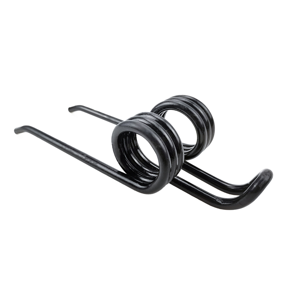
A torsion spring is loaded by rotating its legs, so its rate is torque per unit of angle. With wire diameter d, mean diameter D, active coils N and Young's modulus E, the rate per full turn is:
k′ = E · d⁴ / (10.8 · D · N)
The constant 10.8, rather than the theoretical 10.2, allows for friction between the coils and the arbor (Engineers Edge, Torsion Spring Design, citing Shigley, retrieved 2026-10-07). Divide by 360 to get the rate per degree. For a music wire spring with d = 2.0 mm, D = 16 mm and 6 coils, and E = 30 × 10⁶ psi (about 206.8 GPa, from the same Engineers Edge material table), the rate is about 3,192 N·mm per turn, or 8.87 N·mm/°.
Long legs bend as well as the coils, which lowers the rate. Shigley adds the leg lengths as equivalent coils, (L1 + L2) / (3πD). The European design standard for torsion springs is EN 13906-3. Our torsion spring specification guide works through leg angles, wind direction and torque at a working angle in detail, and our custom torsion springs page lists leg and end options.
Springs in series, in parallel, and progressive springs
When two springs work together, their rates combine in a fixed way.
- In series (stacked end to end, carrying the same force): 1/k = 1/k1 + 1/k2. Two equal springs in series have half the rate and twice the travel.
- In parallel (side by side, deflecting the same amount): k = k1 + k2. Two equal springs in parallel have twice the rate. Nested springs, one inside the other, work in parallel. They are usually wound in opposite directions so the coils do not tangle.
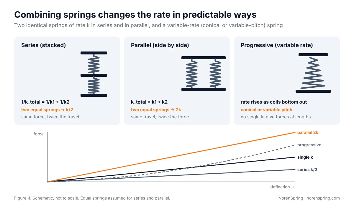
Some springs are made to have a rising rate on purpose. A conical spring or a variable-pitch spring lets its largest or most closely spaced coils bottom out first. Each coil that closes stops being active, so the rate increases with travel. Progressive springs are used where a soft initial feel and a firm end stop are both needed. For these springs, a single rate value means nothing. State the force at each working length instead. Our conical spring guide works through one of these curves and includes a calculator.
Spring rate testing: how to measure spring rate on a tester
Spring rate testing is simple in principle. To measure spring rate, compress or stretch the spring to two lengths inside its linear range and record the force at each. Then divide the difference in force by the difference in length.
- Measure the free length with a height gauge. On a compression spring, measure it after pressing the spring to solid once if the drawing calls for presetting.
- Choose two test lengths between about 20% and 80% of the available deflection. In the worked example, these are 44 mm and 26 mm (6 mm and 24 mm of deflection).
- Record the force at each length on a calibrated spring tester. Approach each length from the same direction, because friction and hysteresis make readings taken while loading and while unloading slightly different.
- Calculate the rate: k = (F2 − F1) / (L1 − L2), or equivalently the force difference divided by the deflection difference (s2 − s1). With the example readings in Figure 1, 18.2 N and 82.0 N, the rate is 63.8 / 18 ≈ 3.54 N/mm. The two-point calculator above does the same sum.
- For extension springs, take both points above initial tension. For torsion springs, record torque at two angles and divide by the angle difference.
ISO 22705-1 defines measurement and test methods for cold formed compression springs, including how to determine spring rate (BSI, EN ISO 22705-1). If you need test results from a supplier, ask for the test lengths, the loading direction and the number of preset cycles, so your incoming inspection measures the same thing.
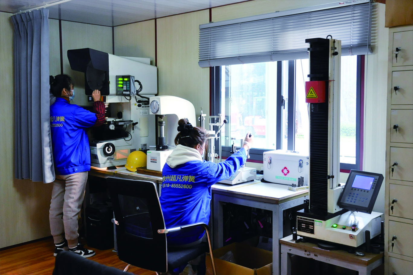
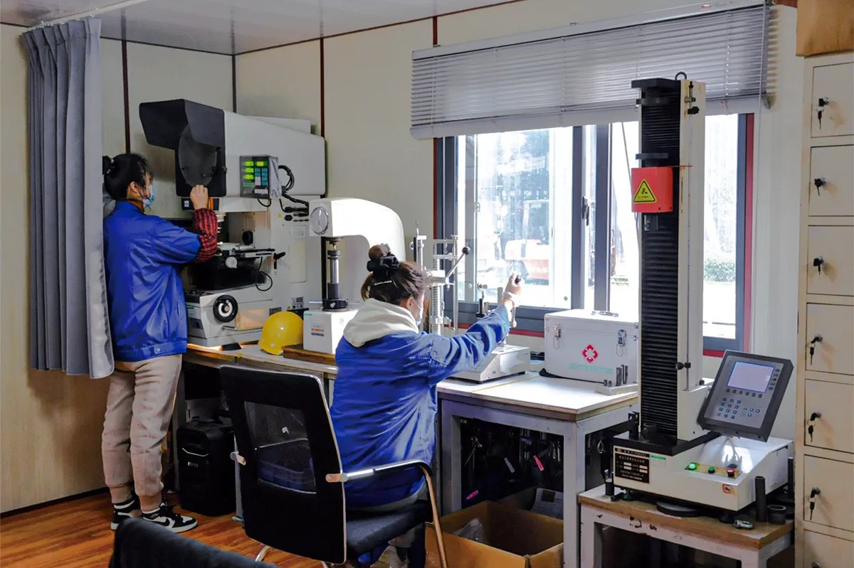
At NorenSpring, rate is checked on the equipment in our in-house laboratory:
| Equipment | Model | What it measures |
|---|---|---|
| Spring tension and compression tester | JISC PRO series / Aikoh 1311NR series | Compression and tension force, rate (K value), working height, maximum load |
| Automatic spring tester | ALGOL PRO-01 series | Rate, free length, initial tension and load, for batch inspection |
| Torsion spring tester | JISC PRO-T / PRO-TT series | Torque, angle and torsional force |
| Height gauge | Mitutoyo LH-600 series | Free height, working height and dimensional tolerances |
| Vision measuring system | Keyence IM-8000 / IM-8030 series | Length, OD, wire diameter, angle and coil count |
Why a measured rate differs from the formula
A measured rate within a few percent of the calculated value is normal. Larger gaps usually have one of these causes.
| Cause | Effect on measured rate | What to do |
|---|---|---|
| Wire diameter at the edge of its tolerance | Rate changes by about 4% for each 1% change in d | Measure d with a micrometer and recalculate |
| Active coil count is not a whole number | Effective coils at the end transitions differ from Nt − 2 | Measure rate on samples and adjust coil count |
| Test points too close to free or solid length | Lower rate at the start, higher rate near solid | Test between 20% and 80% of deflection |
| Initial tension included (extension springs) | Rate overstated if force is divided by extension | Use two points above initial tension |
| Shear modulus varies with material and condition | A few percent difference between grades and suppliers | Use the G value for the actual wire grade |
| Friction on a rod, in a bore or on an arbor | Hysteresis between loading and unloading readings | Test the free spring, then the assembly |
| Spring index very low or very high | Low index: the d⁴/D³ formula is less exact. High index: coils may buckle or tangle | Keep the index between about 4 and 12 where possible |
Heat treatment and stress relief do not change G much, but they do affect how much the spring sets. A spring that takes a permanent set after assembly gets shorter, so the force at a given installed length drops even if the rate looks unchanged.
How to put spring rate on a drawing
For most compression and extension springs, specify the force at two working lengths with a tolerance on each, and give the rate as a reference value. For example: "F1 = 21 N ± 10% at L1 = 44 mm; F2 = 85 N ± 10% at L2 = 26 mm; rate 3.55 N/mm (ref.)". The tolerance values here are only for illustration; agree yours with the supplier.
Notice that the example readings in Figure 1 would fail this callout at L1: 18.2 N is below 18.9 N, because the end coils seat over the first few millimetres, so the straight part of the measured line sits about 3 N below the calculated line. The rate is right, but the force line sits too low. A manufacturer fixes this by adjusting free length, which is why the drawing should leave free length as a reference dimension rather than fixing it as well.
There are three reasons for writing it this way:
- The force line has two degrees of freedom. Rate fixes the slope, but free length tolerance moves the whole line. Two forces at two lengths fix both slope and position.
- Tolerance standards grade force, not rate. EN 15800 sets quality grades for compression spring force at a given length, coil diameter and free length (BSI, EN 15800). DIN 2097 does the same for extension springs.
- The manufacturer needs free variables. If the drawing gives two forces, the spring maker can adjust free length and active coils to hit them. If every dimension is fixed as well, there is nothing left to adjust.
Specify the rate directly, with a tolerance and the two test lengths, only when the slope itself drives the function. Examples include pressure relief valves, force-balancing mechanisms and measuring instruments. In that case, mark free length as a reference dimension.
Spring rate checklist for your RFQ
| Item | What to send |
|---|---|
| Spring type | Compression, extension, torsion, conical or variable pitch |
| Working points | Force (or torque) at two lengths (or angles), with tolerances |
| Rate | Reference value, or a toleranced value with test lengths if it is functional |
| Space limits | Maximum OD or minimum ID, rod or bore size, solid or maximum length |
| Extension springs | Initial tension, if a minimum pull before movement matters |
| Material and environment | Wire grade or the corrosion and temperature conditions |
| Testing | Test lengths, presetting, sample size and whether you need a test report |
| Quantity | Prototype and annual volume |
If you only have a sample, send it or send measurements and photos. We can measure the geometry, test the force at two lengths and propose a drawing for your approval. Most projects start from a drawing or sketch, and we usually give engineering feedback within 24 hours. Samples take 7 to 15 working days and production 15 to 30 working days, depending on the spring. You can reach our engineers through the contact page or see our manufacturing capabilities.
Frequently asked questions
Is spring rate the same as spring constant?
Yes. Both describe the force needed per unit of deflection, k in Hooke's law F = k·x. "Spring constant" is common in physics. "Spring rate" is the usual term on drawings and in the spring industry. For torsion springs, the equivalent is torque rate, in N·mm per degree.
How do I find the rate of a spring I already have?
Measure it, or calculate it. To measure, compress the spring to two lengths between about 20% and 80% of its travel, read the force at each, and divide the force difference by the length difference. To calculate, measure the wire diameter with a micrometer and the outside diameter, count the total coils, identify the end type, and use the calculator above.
Is a higher spring rate better?
No. A higher rate gives more force for the same travel, but it also raises stress for the same travel, which can shorten fatigue life. It also makes the force more sensitive to assembly tolerances. Choose the lowest rate that still gives the forces you need at your working lengths.
How do I convert N/mm to lbf/in?
Multiply by 5.71. A rate of 3.55 N/mm equals about 20.3 lbf/in. To go from lbf/in to N/mm, multiply by 0.175. For torsion springs, 1 N·mm/° equals about 0.00885 lbf·in/°. Whichever unit you use, state per degree or per turn clearly on the drawing.
What tolerance can a manufacturer hold on spring rate?
It depends on the spring index, the number of active coils, the wire tolerance and the quality grade you specify. Standards such as EN 15800 grade the force tolerance rather than rate. Send your working points and we will confirm what can be held at the quotation stage.
About the authors
This guide was prepared by the NorenSpring engineering team, which designs and manufactures custom compression, extension and torsion springs and wire forms in Xuzhou, China. Technical review by Feng Yulin, General Manager and senior structural engineer, who has 15 years of spring R&D experience and more than 30 national patents. NorenSpring holds IATF 16949, ISO 9001, ISO 13485, ISO 14001 and ISO 45001 certifications. More about NorenSpring.
Sources
- R. G. Budynas and J. K. Nisbett, Shigley's Mechanical Engineering Design, McGraw-Hill, chapter 10, Mechanical Springs. Source for the compression, extension and torsion rate formulas, active coils by end type, Na = Nb + G/E and the leg allowance.
- Engineers Edge, Helical Compression Spring Design. Source for the 20% to 80% measuring range and central 60% design range. Retrieved 2026-10-07.
- Engineers Edge, Spring Material and Types Data. Source for the shear modulus and Young's modulus values. Retrieved 2026-10-07.
- Engineers Edge, Extension Spring Force Formula and Torsion Spring Design. Retrieved 2026-10-07.
- BSI, EN 13906-1 and EN 13906-2, calculation and design of compression and extension springs. Retrieved 2026-10-07.
- BSI, EN 15800, Quality specifications for cold coiled compression springs. Retrieved 2026-10-07.
- BSI, BS EN ISO 22705-1:2025, Springs. Measurement and test parameters. Cold formed cylindrical helical compression springs. Retrieved 2026-10-07.
- DIN, DIN 2097, Quality specifications for cold coiled tension springs. Retrieved 2026-10-07.