

In this article
- Key takeaways
- What is a conical spring?
- Conical, tapered, double conical (barrel), hourglass and volute springs: what the names mean
- Why engineers choose a conical spring
- How far must the diameter step for the coils to telescope?
- How the load curve works: coils bottom out one by one
- Constant pitch or variable pitch: progressive or near-linear force
- Stress: where a conical spring works hardest
- Conical spring calculator
- What to put on your drawing or request for quote
- Frequently asked questions
- Summary: decide what the taper is for
- About the authors
- Sources
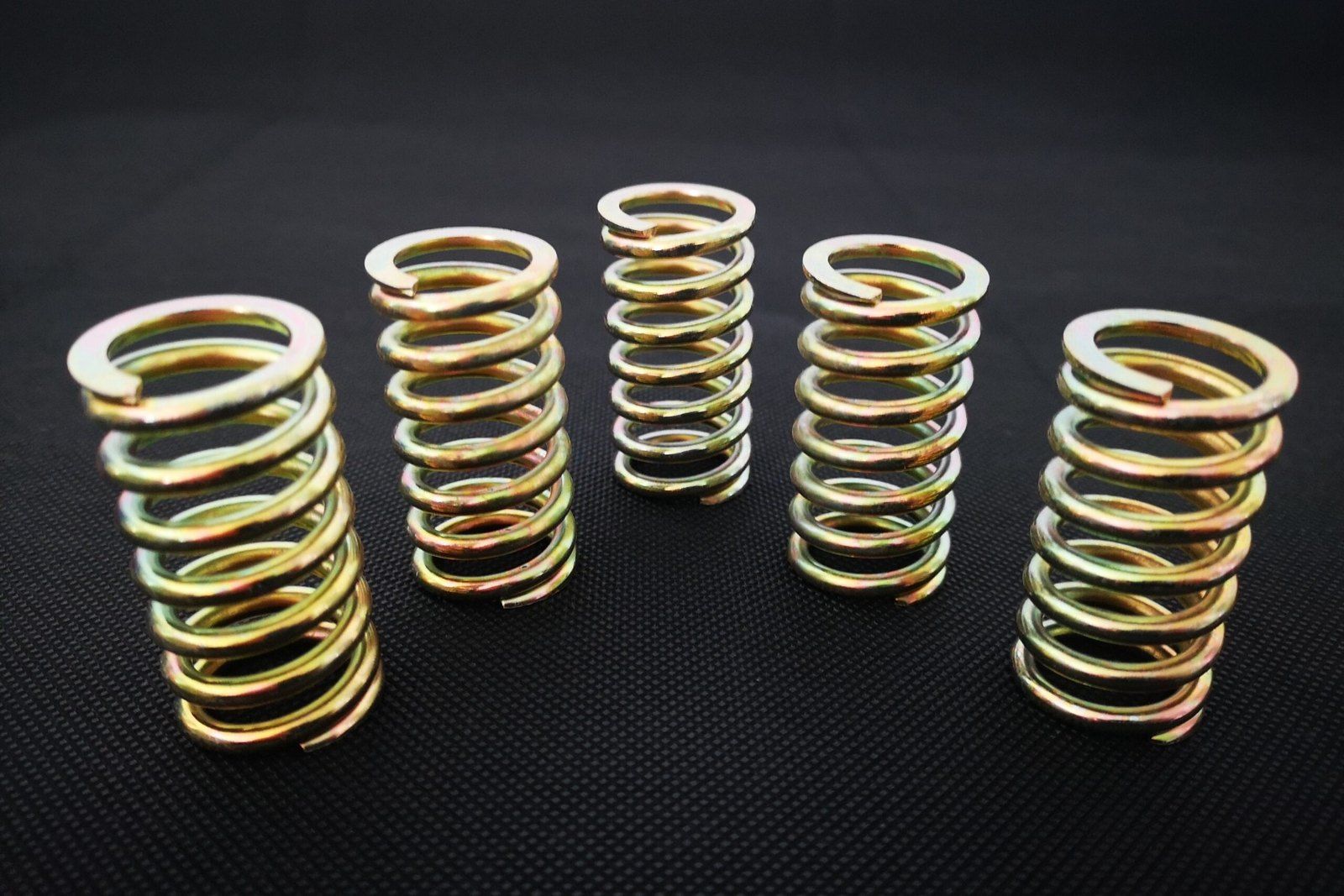
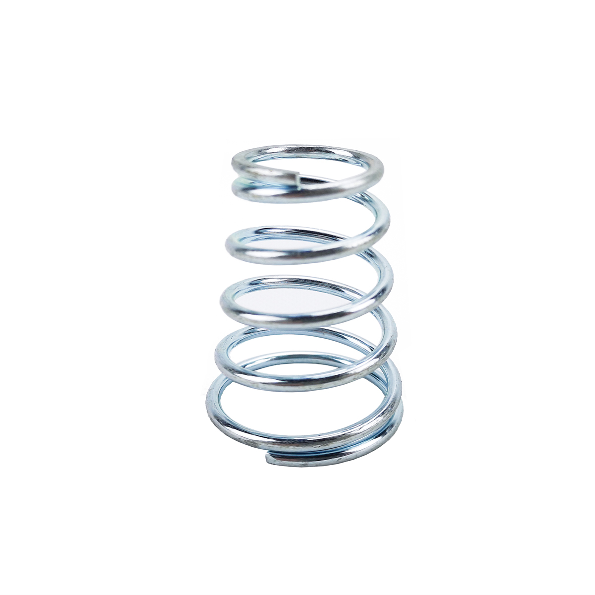
A conical spring is a compression spring wound from a large diameter at one end to a small diameter at the other. That taper does three things a straight spring cannot: if the taper is steep enough, the coils slide inside each other, so the spring closes to about one or two wire diameters; the wide end gives a stable seat, so it is less likely to buckle; and the large coils bottom out first, so the force rises faster as the spring is compressed. If you need any of those, a conical compression spring is worth considering.
This guide explains what the names conical, tapered, double conical, barrel, hourglass and volute mean, how far the diameter has to step for the coils to nest, why the load curve stiffens, where the stress ends up, and what to put on a drawing or request for quote. A free conical spring calculator is included, and every number in the worked example can be checked with it.
Key takeaways
- Telescoping needs a step of more than two wire diameters. Each turn’s mean diameter must be smaller than the next by 2 × the wire diameter plus a clearance. Then the active turns can close to about one wire diameter, and the whole spring to about one or two.
- The curve is straight until the largest coil closes. In the worked example the rate is 1.44 N/mm for the first 6.4 mm, then the load climbs from 9.1 N to about 161 N over the last 9.6 mm.
- Stress ends up in the small coils. At any load the largest free coil is the most stressed, but in a constant pitch spring pushed to solid the small coils close last, under the highest load. In the example the peak stress more than doubles in the last 2 mm of travel.
- Ask for a straight line if you need one. Varying the pitch so all coils close at about the same time keeps the force close to linear.
- Specify both diameters, the heights and one or two loads. Let the manufacturer choose pitch and turns to meet them.
What is a conical spring?
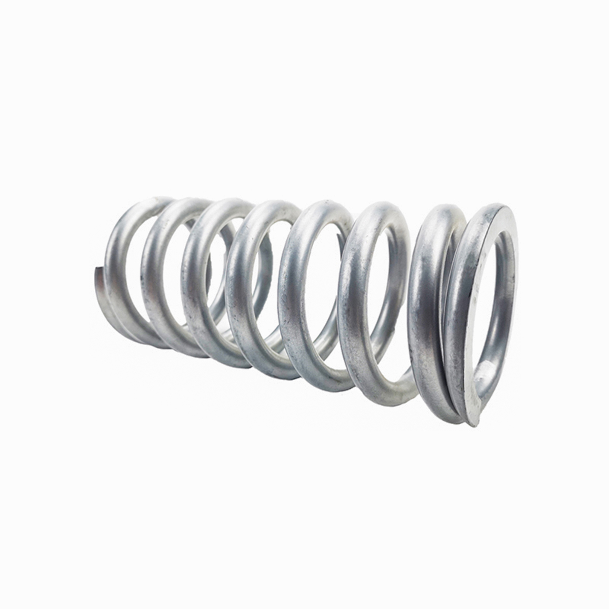
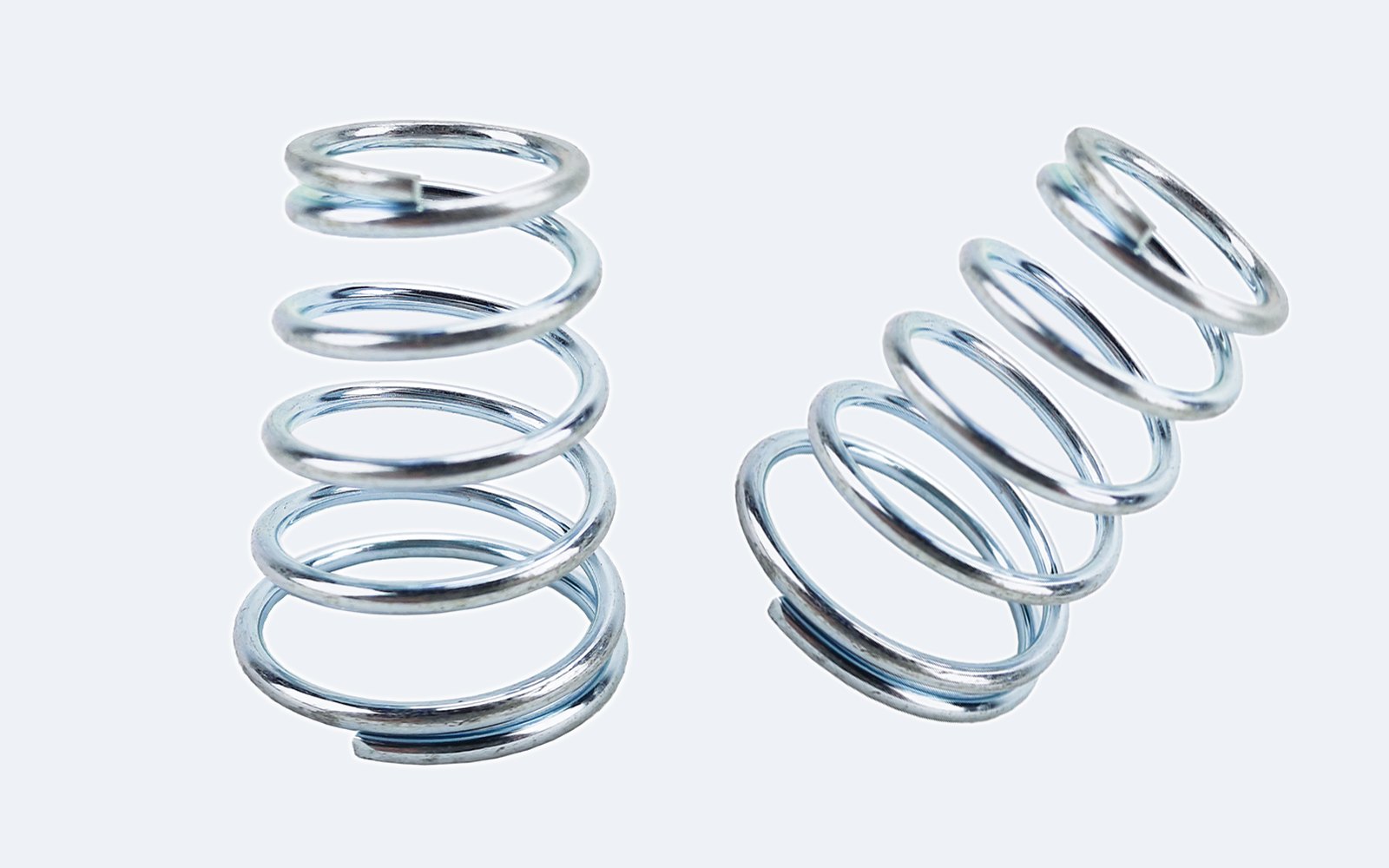
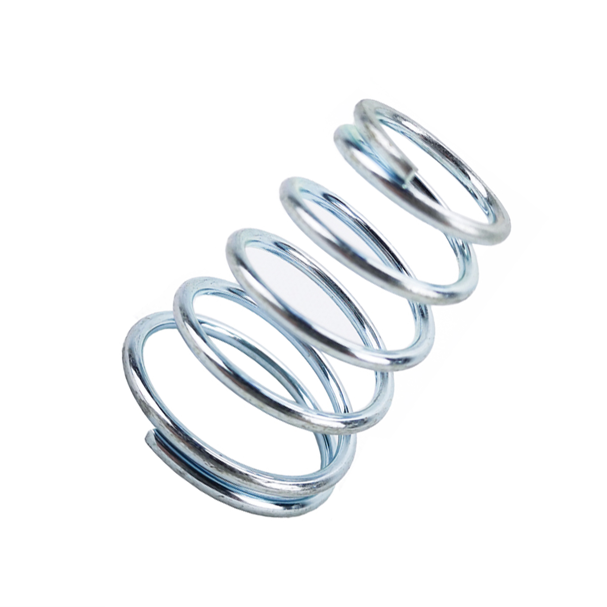
A conical spring is a helical compression spring whose coil diameter changes steadily from one end to the other, so its outline is a cone. It is also called a tapered spring or a cone spring. Most are made from round wire and work like any compression spring: push the ends together and the wire twists, storing energy. The difference is that each coil has a different diameter, and a coil’s stiffness depends on the cube of its diameter. A coil twice as wide is about eight times softer.
That one fact explains everything else in this guide. Because the large coils are the soft ones, they deflect most and close first. Because each closed coil stops working, the spring gets stiffer as it is compressed. And because the coils differ in size, a well-designed taper lets each one drop inside its neighbour instead of landing on top of it.
Conical, tapered, double conical (barrel), hourglass and volute springs: what the names mean
Catalogues use these names loosely. They describe four shapes; one of them, the volute, is often made from strip rather than round wire.
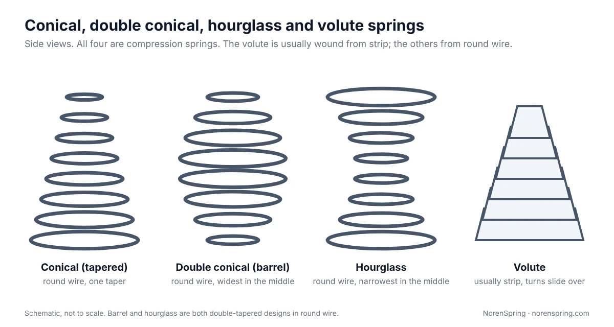
| Name | Shape | Material | What it gives |
|---|---|---|---|
| Conical, tapered, cone | One taper, large end to small end | Round wire | Low solid height, a stable large end, a progressive rate |
| Double conical, barrel | Widest in the middle, small at both ends | Round wire | Small ends that locate on pins; each half can nest like a conical spring if its taper is steep enough |
| Hourglass, concave | Narrowest in the middle, wide at both ends | Round wire | Two wide, stable ends |
| Volute | A cone whose turns slide over each other; often wound from strip or plate | Strip, plate or wire | Very short closed length; historically used in heavy buffers |
“Volute” is the one name that is used two ways. Merriam-Webster defines a volute spring as a conically spiral coil of plate, rod or wire [6], and the Wikipedia article on volute springs opens by calling it another name for a conical spring [1]. Wikipedia’s examples, though, are mostly heavy springs whose steel starts as a V shape, one end wider than the other: double volute springs in garden pruning shears, railway buffers going back to a design by John Brown in 1848, and the suspension of the M4 Sherman tank [1]. In a request for quote, check what is meant. If a drawing says “volute” but shows round wire, it describes a conical spring.
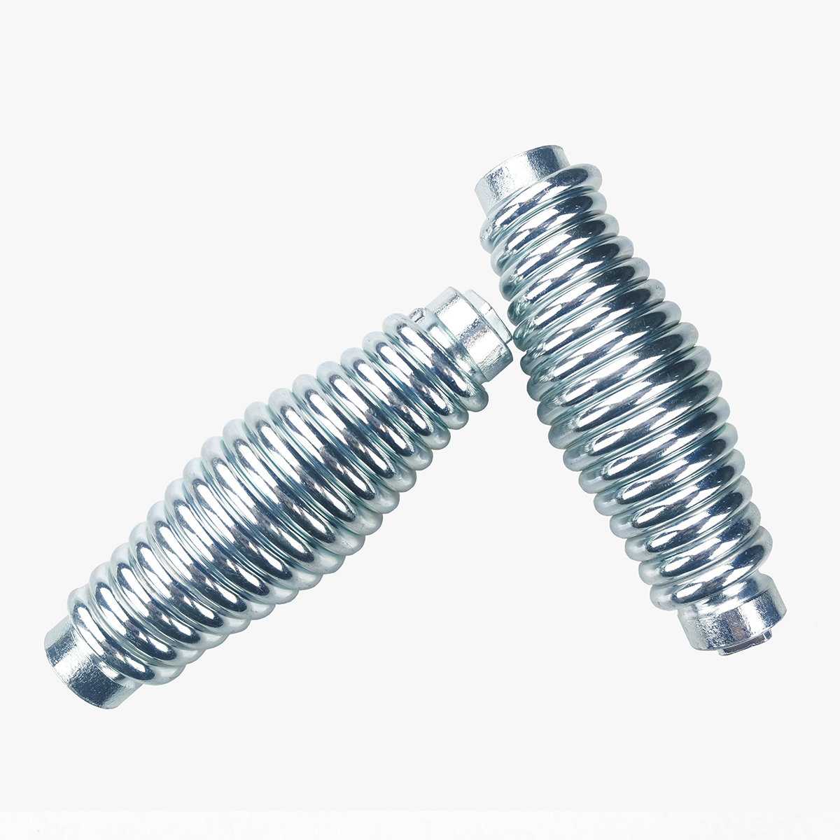
Barrel and hourglass springs are the two double-tapered shapes. A barrel spring has two small ends that can locate on pins or bosses, and each half behaves like a short conical spring. An hourglass spring has two wide ends and a narrow waist. Both are specified the same way as a conical spring, with the diameters at the ends and at the middle.
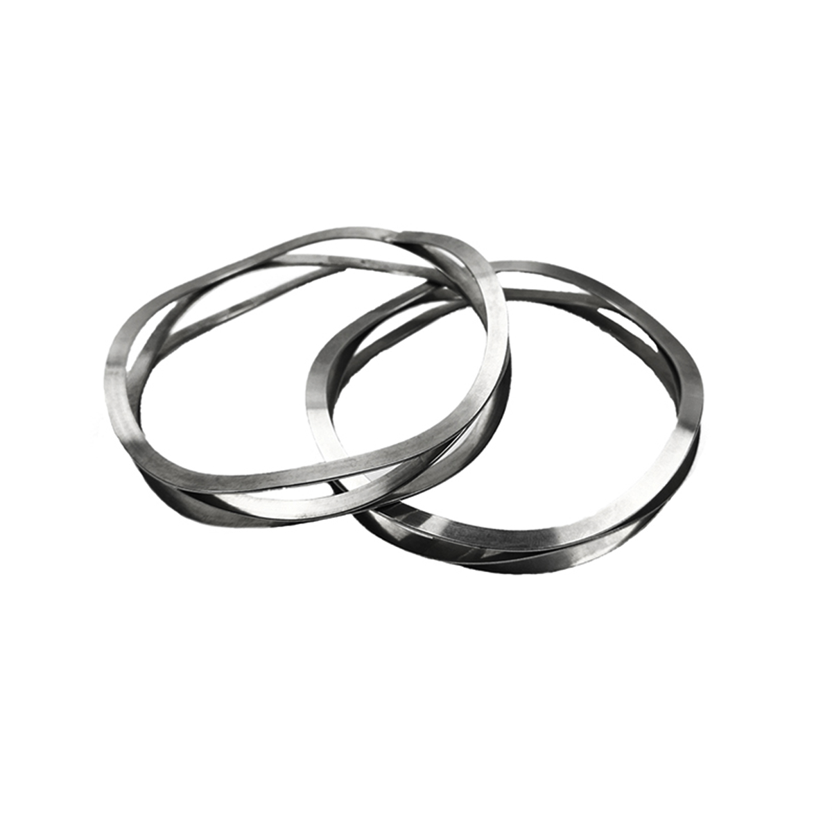
Do not confuse any of these with a disc spring or Belleville washer, which is a single coned ring rather than a coil. Our disc spring guide covers those.
Why engineers choose a conical spring
The three reasons below come straight from the geometry. Our conical springs page lists molds, dies, stamping tools, precision machinery, automotive components and electrical devices among the typical applications.
Low solid height. A straight spring at solid is a stack of wire: four active turns of 1.2 mm wire are at least 4.8 mm tall, before counting the end coils. A fully telescoping conical spring with the same wire closes its active turns to about 1.2 mm. Our product page gives battery cells, push buttons and valve plates as places where that height saving is used. Battery contact uses are covered on our electronics industry page.
Stability. The wide end sits on a broad seat, so, as our product page puts it, the spring is less likely to buckle sideways.
A rising force. Because the coils close one after another, the force grows faster near the end of the stroke. That cushions the end of travel and is useful where a soft start and a firm finish are wanted. Paredes notes that this non-linear behaviour is exploited in some applications, such as vibration absorbers [2].
The trade-offs: a fully nesting design limits how many turns fit between the two diameters, which limits the travel; the spring is harder to guide on a rod because its inside diameter changes; and it needs more care in design because its rate is not a single number.
How far must the diameter step for the coils to telescope?
For one turn to slide inside the next, its outside diameter must be smaller than the inside diameter of the next larger turn. A turn’s outside diameter is its mean diameter plus one wire diameter, and its inside diameter is its mean diameter minus one wire diameter. So the mean diameter has to drop by more than two wire diameters per turn, plus a clearance so the turns do not rub. The same rule appears on our product page, and the Paredes paper uses it as the condition for a spring that fully telescopes [2].
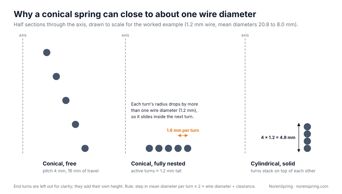
Worked example. Take 1.2 mm wire, a large end of 22 mm outside diameter and a small end of 9.2 mm, with 4 active turns. The mean diameters are 20.8 mm and 8.0 mm, so each turn steps down by (20.8 − 8.0) ÷ 4 = 3.2 mm. Two wire diameters are 2.4 mm, which leaves 0.8 mm, or 0.4 mm of clearance per side. The spring telescopes. Paredes notes that a fully telescoping conical spring has a solid length equal to the wire diameter [2]; in practice the end coils add their own height, which is why our product page says about one to two wire diameters.
If the taper is too gentle, the turns land on each other instead. The spring still has a progressive rate, but its solid height is close to that of a straight spring. Partial nesting is also possible: the large turns may nest while the smaller ones stack. Say on the drawing whether the coils must nest fully, partly or not at all.
How the load curve works: coils bottom out one by one
With an even pitch, all active turns start with the same gap, but the large turns are the softest, so they use up their gap first. Until the largest turn closes, the spring behaves like an ordinary spring with a single rate. For a constant pitch conical spring that rate is:
k = G d⁴ ÷ [2 Na (D₁ + D₂)(D₁² + D₂²)]
where G is the shear modulus of the wire, d the wire diameter, Na the number of active turns and D₁ and D₂ the smallest and largest mean diameters. With G in MPa (N/mm²) and all lengths in mm, k is in N/mm. This is the initial flexibility of a constant pitch conical spring given by Rodriguez and quoted by Paredes [2][3]. It is also what you get by adding up the standard per-coil flexibility 8D³ ÷ (G d⁴) along the taper [2][4], which is how our calculator works.
Once the largest turn closes, it stops deflecting, fewer turns remain active and the rate rises. Each further turn that closes raises it again, so the curve bends upward until the smallest turn closes and the spring is solid.
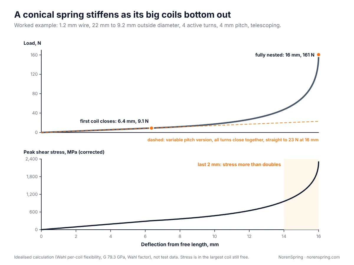
Worked example, continued. With hard-drawn spring wire (G = 79.3 GPa, the value used in our spring rate guide [7]) and a 4 mm pitch:
- The initial rate is 79,300 × 1.2⁴ ÷ [2 × 4 × 28.8 × (8.0² + 20.8²)] ≈ 1.44 N/mm.
- The largest turn closes when it has used up its 4 mm of travel, the full pitch, because a telescoping turn slides inside its neighbour rather than landing on it. That happens at about 6.4 mm and 9.1 N.
- The spring is fully nested at 16 mm of travel, when the smallest turn closes, at about 161 N.
In other words, the first 40% of the travel needs less than 6% of the final load. The same wire wound as a straight spring at the large end’s diameter, with 4 active turns, would have a single rate of about 0.57 N/mm, but its 4 active turns would stack to at least 4.8 mm at solid instead of about 1.2 mm (Figure 2).
Constant pitch or variable pitch: progressive or near-linear force
A constant pitch conical spring is progressive, as shown above. If the application needs a straight-line force, for example to hold a predictable preload across a tolerance range, the pitch can be varied along the taper so that the large turns get larger gaps and the small turns smaller ones; in the ideal case each gap grows with the cube of the turn’s diameter. Sized correctly, all turns close at about the same time and the force stays close to linear until the spring is solid.
The dashed line in Figure 3 shows this for the worked example. Keep the wire, the diameters, the 4 active turns and the 16 mm of travel, but make each turn’s gap proportional to the cube of its diameter: about 10 mm at the large end and about 0.6 mm at the small end, which is less than the wire diameter and works only because the turns nest. The rate then stays at 1.44 N/mm all the way, and the spring reaches solid at about 23 N instead of 161 N. Because every turn closes under that same 23 N, the peak stress at solid is about 760 MPa, in the largest turn, instead of about 2,300 MPa in the smallest. The cost is that it never gives the firm end-of-stroke force of the progressive design.
Paredes shows that a conical spring can have a constant pitch, a constant helix angle, a constant stress at solid or a linear load-length relation, but only one of these at a time, whereas a straight spring can have all four at once [2]. So a drawing that says “conical, linear rate” is a design choice the manufacturer has to make on purpose, not a default. Tell us which behaviour you need, or give two load points at two heights and we will design to them within agreed tolerances.
Stress: where a conical spring works hardest
At any given load, the most stressed turn is the largest one that is still free, because the twisting moment on the wire is the load times the turn’s radius. Early in the stroke that is the large end.
The picture changes near solid. In a constant pitch spring, the small turns close last, under the highest load. Apply the uncorrected shear stress formula used by Paredes, 8PD ÷ (πd³), to each turn as it closes and the result is clear: a small turn closing under a large load carries more stress than the large turns did when they closed [2]. In the worked example, the peak stress with the Wahl correction is about 300 MPa when the first turn closes and about 960 MPa at 14 mm, then rises to about 2,300 MPa as the last turn closes at 16 mm (Figure 3). The last 2 mm of travel more than doubles it. Stress at that level is far above what 1.2 mm hard-drawn wire can take (see our spring wire material guide for the grades), so this example spring would take a permanent set if pushed fully solid. In a real design the travel would be limited, for example to about 12 mm, where the peak stress is about 650 MPa, or the small end would be redesigned.
That leads to three practical rules:
- Do not use full nesting as a working position unless the stress at solid has been checked against the allowable stress for the wire grade and size. Our spring wire material guide explains the grades.
- Keep the working height above the steep part of the curve if the spring cycles. Small changes in height there cause large changes in both load and stress, and fatigue life depends on the stress range each cycle, so tell the manufacturer the two heights the spring cycles between.
- If the spring must go solid, say so. The manufacturer can then design for it, for example with a smaller gap at the small end, a constant stress design or a different wire.
Conical spring calculator
Enter your wire diameter, the two outside diameters, the active turns, the pitch and the material. The calculator gives the initial rate, when the first turn closes, and the load and peak stress at five points through the travel. It also checks whether the turns can telescope.
Conical spring calculator
Constant pitch, round wire. Gives the initial rate, when the first coil closes, and load and peak shear stress through the travel.
Idealised model: per-coil flexibility 8D³ ÷ (G d⁴) summed along the taper, the largest free coil closing first; stress 8PD ÷ (πd³) with the Wahl factor in the largest coil still free. End coils, friction and manufacturing tolerances are not included. Use the result to compare designs; the manufacturer confirms the final design and its load tolerance.
The calculator uses the same idealised model as Figure 3. It ignores the end turns, friction between turns and manufacturing tolerances, and it treats the gap of a non-telescoping turn as the pitch minus the wire diameter. Use it to compare designs and to check that a load is in the right range. For how rate is measured and toleranced on a straight spring, see our spring rate guide.
What to put on your drawing or request for quote
A conical spring is specified by its envelope and what it must do. The manufacturer then chooses the pitch and the number of turns. Send:
- Large-end outside diameter and small-end outside diameter, and which end is held by a bore, a boss or a pin.
- Wire diameter, if it is fixed; otherwise leave it to the designer.
- Free length, and the lowest height the spring may reach in use.
- One or two loads at stated heights, for example 10 N at 12 mm and 40 N at 6 mm. Two points let the designer set the shape of the curve.
- Nesting: must the turns telescope fully, partly or not at all?
- Rate behaviour: progressive, as wound with an even pitch, or close to linear.
- End type at each end, such as closed, or closed and ground for a flat seat on the large end.
- Material and finish, plus the operating temperature and environment.
- Duty: static, occasional or cycling, and the expected number of cycles.
- Quantity, and whether you need samples first.
If you already have a straight compression spring that is too tall at solid, send its drawing with the height you need; that is often the quickest way to start. For straight springs, see our straight compression springs made to order; our guide to specifying a custom compression spring lists the equivalent information.
Frequently asked questions
What is the difference between a conical spring and a tapered spring?
None. Conical spring, tapered spring and cone spring are three names for a round-wire compression spring whose diameter changes from one end to the other.
Is a volute spring the same as a conical spring?
Sometimes. Wikipedia treats the two names as the same thing, and Merriam-Webster’s definition covers plate, rod or wire [1][6]. In practice “volute” is often used for heavy cone-shaped springs wound from strip, such as old railway buffers, while “conical” usually means round wire. If a drawing uses either word, the cross-section shown on it decides.
Can a small conical spring telescope?
Yes, if each turn’s mean diameter drops by more than two wire diameters plus clearance. Small conical springs for battery contacts and push buttons can be designed to nest fully. With a fine wire the clearance per side becomes small, so diameter tolerances need checking.
Why does my conical spring get stiffer as it compresses?
Because its large turns are softer and close first. Each closed turn stops deflecting, so fewer turns share the load and the rate rises. A varied pitch can keep the rate close to constant if that is what you need.
How do I calculate the rate of a conical compression spring?
For a constant pitch spring, before any turn closes, k = G d⁴ ÷ [2 Na (D₁ + D₂)(D₁² + D₂²)], using the mean diameters at the two ends. After the first turn closes the rate is not constant, so use the calculator or a turn-by-turn calculation.
Do you make conical springs to drawing?
Yes. We make round-wire conical compression springs to drawings, samples or performance requirements. Send the details listed above through our contact page and our engineers will confirm the design and the load tolerance.
Summary: decide what the taper is for
A conical spring is chosen for one of three reasons: a low solid height, a stable seat, or a rising force. Decide which matters most before you specify it. If you need the spring to nest, check that each turn steps down by more than two wire diameters. If you need a predictable force, give two load points and say whether the curve should be progressive or close to linear. And if the spring will be pushed close to solid, have the stress at the small end checked. To get a custom conical compression spring quoted, send your dimensions, loads and quantity through the contact page.
About the authors
This guide was prepared by the NorenSpring engineering team, which designs and manufactures custom springs and wire forms in Xuzhou, China. Technical review by Feng Yulin, General Manager and senior structural engineer, who has 15 years of spring R&D experience and more than 30 national patents. NorenSpring holds IATF 16949, ISO 9001, ISO 13485, ISO 14001 and ISO 45001 certifications. More about NorenSpring. Figures and calculations were last checked on 12 October 2026.
Sources
The numbers in square brackets in the text refer to this list.
- Wikipedia, Volute spring. Source for the description of volute springs, double volute springs in pruning shears, the 1848 railway buffer by John Brown and the M4 Sherman suspension. Retrieved 2026-10-12.
- M. Paredes, “Analytical and experimental study of conical telescoping springs with non-constant pitch“, Journal of Mechanical Design, vol. 135, no. 9, 2013 (author’s preprint on arXiv). Source for the per-coil stress and flexibility, the initial flexibility of a constant pitch conical spring, the solid length of a fully telescoping spring, the four design types of which only one can be achieved at a time, and the use of non-linear conical springs in vibration absorbers. Retrieved 2026-10-12.
- J. Rodriguez, M. Paredes and M. Sartor, “Analytical behavior law for a constant pitch conical compression spring”, Journal of Mechanical Design, vol. 128, no. 6, 2006. Original source of the constant pitch flexibility formula, as cited in [2].
- A. M. Wahl, Mechanical Springs, 2nd edition, McGraw-Hill, 1963. Standard reference for helical spring stress, deflection and the Wahl correction factor, cited in [2].
- NorenSpring engineering team, idealised calculations for Figures 2 and 3 and the calculator, 2026-10-12. Per-coil flexibility summed along a linear taper with the largest free coil closing first; the linear part checked against the closed-form formula in [2] (both give 1.44 N/mm for the worked example) and the closing loads checked by hand.
- Merriam-Webster, volute spring. Source for the definition as a conically spiral coil of plate, rod or wire. Retrieved 2026-10-12.
- Engineers Edge, Spring Material and Types Data. Source for the shear modulus values in the worked example and the calculator, as used in our spring rate guide. Retrieved 2026-10-12.