

In this article
- Key takeaways
- What is a disc spring?
- The four dimensions that define a disc spring
- How h0/t shapes the load curve
- Disc spring calculator
- Stacking disc springs (Belleville washer stacks): series, parallel and combined
- Disc spring materials and finishes
- Disc spring vs DIN 6796 conical spring washer vs wave spring
- Static vs dynamic loading and fatigue
- What to include in a disc spring RFQ
- Frequently asked questions
- About the authors
- Sources
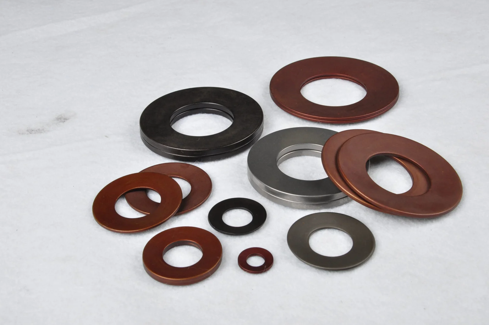
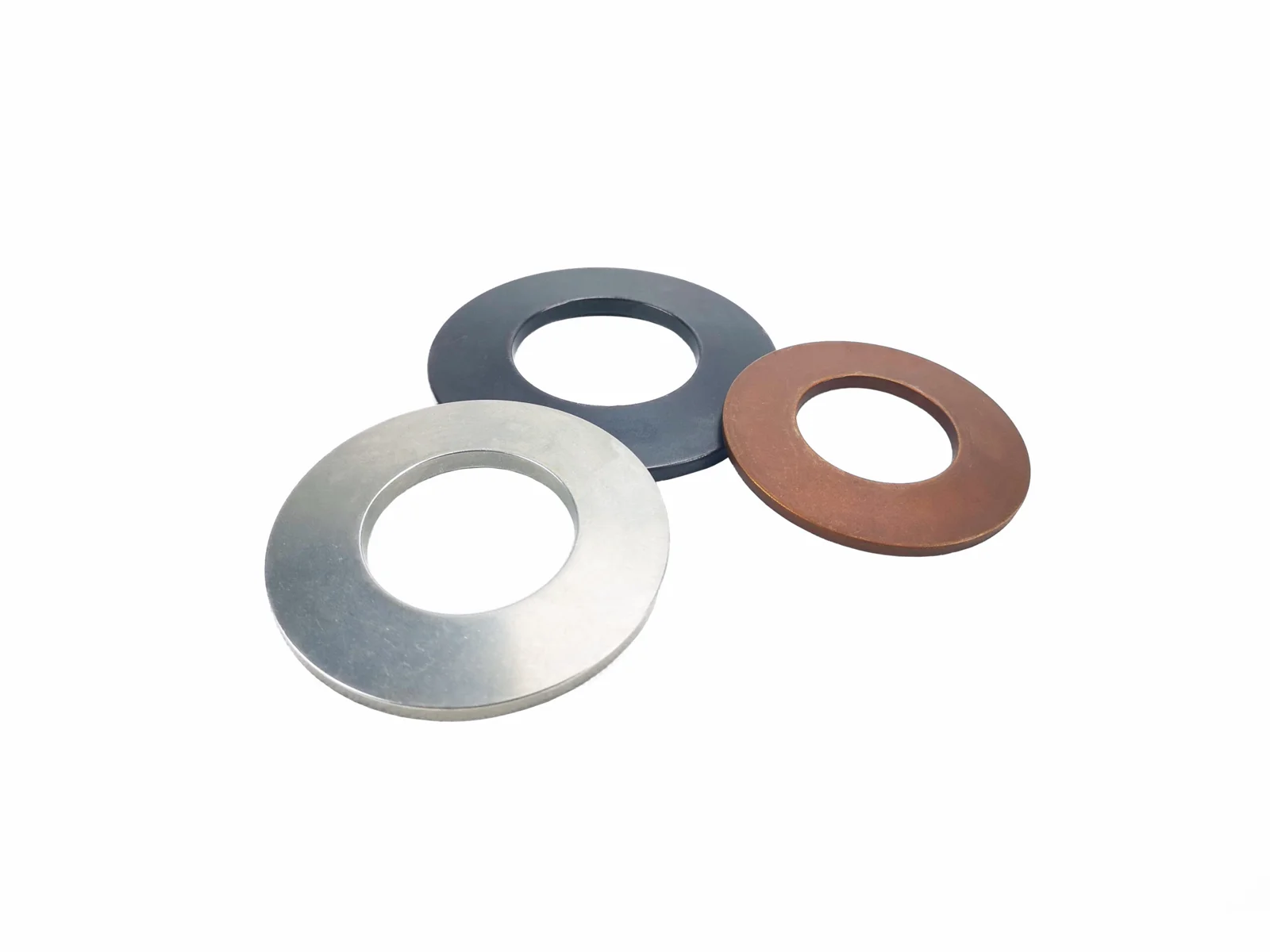
A disc spring, also called a Belleville washer, Belleville spring or conical spring washer, is a cone-shaped steel ring that produces a large axial force over a short travel when you press it flat. One 40 mm disc spring 2.25 mm thick can push back with about 6,500 N after only 0.68 mm of travel. A coil spring of the same outside diameter cannot do that in so little height.
Disc springs are rarely used one at a time. You stack them face to face to get more travel, or nest them in the same direction to get more force, and the mix decides the load curve. This guide explains the four dimensions that define a disc spring and how the ratio of cone height to thickness (h0/t) shapes the curve. It also covers stacking and guiding, materials and finishes, fatigue checks, and what to send when you need a custom part. A free disc spring and stack calculator is included.
Key takeaways
- h0/t sets the curve. At h0/t 0.4 the force rises almost in a straight line. At 1.3 it flattens near the flat position. Above about 1.41 the force falls again before the disc is flat.
- Stacking multiplies. n discs nested in parallel give about n times the force. i discs face to face in series give i times the travel. Two in parallel times three in series turns one 6.5 kN disc into a 13 kN stack with 2.0 mm of travel.
- Design to 75% of h0. EN 16983 tables quote force at 75% of the cone height. Near flat, the real force rises faster than the equation predicts.
- Fatigue lives at points II and III. For dynamic loads, check the tensile stress range on the underside edges and keep a preload so the disc never springs back to free height.
What is a disc spring?
A disc spring is a washer pressed into a shallow cone. Load it on the cone’s top and bottom edges and the cone flattens, storing energy like a spring. The name “Belleville” comes from Julien Belleville, who patented a spring based on the principle in Dunkirk, France, in 1867. “Disc spring”, “Belleville washer”, “Belleville spring”, “disc washer”, “conical disc spring” and “coned-disc spring” all describe the same part. Standards bodies tend to say disc spring. Fastener catalogues tend to say Belleville washer.
Disc springs make sense when you need a high force in a small height. Typical jobs include:
- preloading bolted joints that relax or expand with temperature;
- clamping and releasing tools, such as in machine tool spindle drawbars;
- holding valve seats closed and setting relief pressures in hydraulic valves;
- preloading ball bearings to remove play;
- absorbing shock in short-stroke buffers and overload clutches.
They are not the right part when you need long travel. A single disc only travels a fraction of its own thickness. Stacking adds travel, but a long stack needs a guide and adds friction. A compression spring is usually simpler past a few millimetres of stroke.
The four dimensions that define a disc spring
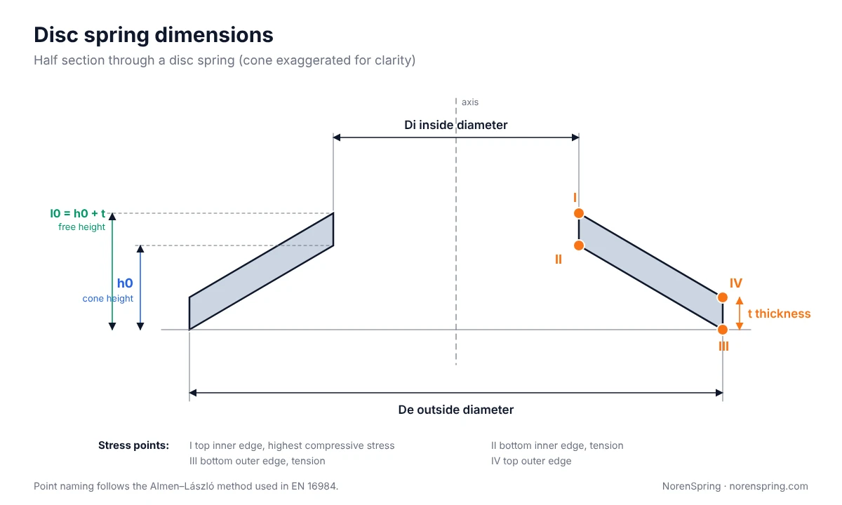
Every disc spring is fixed by four numbers. Get them right on the drawing and a maker can calculate the load curve before cutting any steel.
| Symbol | Name | What it controls |
|---|---|---|
| De | Outside diameter | Fit in the bore or sleeve, and the lever arm for the load |
| Di | Inside diameter | Fit on the guide rod or bolt; De/Di is usually close to 2 |
| t | Thickness | Force rises roughly with t³ to t⁴, so thickness tolerance matters most |
| h0 | Cone height (free height minus thickness) | How far the disc can travel before it is flat |
The free height is l0 = h0 + t. Disc springs are often listed as De × Di × t, for example 40 × 20.4 × 2.25, with l0 given separately.
EN 16983 sorts standard disc springs into three series by shape. Series A is the stiff, thick series, with De/t about 18 and h0/t about 0.4. Series B sits in the middle, at about 28 and 0.75. Series C is the soft, thin series, at about 40 and 1.3. The same standard groups discs by thickness. Group 1 covers discs thinner than 1.25 mm. Group 2 runs from 1.25 to 6 mm. Group 3 covers discs from 6 to 14 mm thick, which have small flats ground on the load edges and a slightly reduced thickness to compensate.
How h0/t shapes the load curve
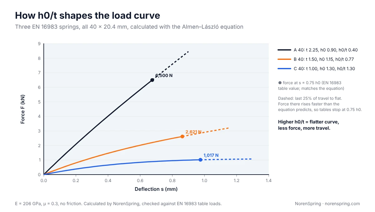
The ratio of cone height to thickness, h0/t, decides the shape of a disc spring’s force–deflection curve. A low ratio gives a nearly straight line. A high ratio gives a curve that flattens out, so the force stays almost constant over part of the stroke. This is the feature that lets disc springs hold a bolt preload steady while the joint settles.
The force is calculated with the Almen–László equations, which EN 16984 (formerly DIN 2092) uses. For a disc without contact flats:
F = [4E / (1 − μ²)] × [t⁴ / (K1 × De²)] × (s/t) × [(h0/t − s/t)(h0/t − s/2t) + 1]
Here s is the deflection, E is Young’s modulus (206,000 MPa for spring steel) and μ is Poisson’s ratio (0.3). K1 depends only on the diameter ratio δ = De/Di:
K1 = (1/π) × [(δ − 1)/δ]² / [(δ + 1)/(δ − 1) − 2/ln δ]
We ran the equation for three standard 40 × 20.4 mm discs, one from each series. At 75% of h0 it gives 6,500 N, 2,621 N and 1,017 N. EN 16983‘s tables list 6,500 N, 2,620 N and 1,020 N, so the equation and the standard agree.
When you read a curve, keep these in mind:
- The dashed last quarter is optimistic. As a disc approaches flat, its contact points move inward, the lever arm gets shorter and the force climbs faster than the equation predicts. That is why tables stop at 0.75 h0 and why you should design the working point there or below.
- High h0/t means sensitivity. On a flat curve, a 0.05 mm difference in installed height barely changes the force. But a small error in h0 or t moves the whole plateau up or down. Tolerances on t and h0 matter more for series C than for series A.
- Above h0/t ≈ 1.41 the force falls before the disc is flat. The curve rises to a peak and then drops. That gives a snap-through action, useful in some switches but unstable in a stack. For a normal spring, keep h0/t at or below about 1.3.
Disc spring calculator
Enter the dimensions of one disc and how you plan to stack it. It works for any disc spring stack or Belleville washer stack. The calculator gives the disc and stack force at 25%, 50%, 75% and 100% of h0, the stack length at each point, the average stack rate and the calculated stresses. The default values are the series A 40 × 20.4 × 2.25 mm disc from Figure 2.
Disc spring and stack calculator
| Position | Disc travel s (mm) | Disc force (N) | Stack travel (mm) | Stack force (N) | Stack length (mm) |
|---|
Almen–László equations as used in EN 16984, for discs without contact flats (K4 = 1), Poisson’s ratio 0.3, friction ignored. Parallel stacks need more force to compress and give back less force when they unload. The force near flat is usually higher than calculated, which is why the 100% row is shown for reference only. Results are estimates for comparing options, not a substitute for a manufacturer’s load test.
Stacking disc springs (Belleville washer stacks): series, parallel and combined
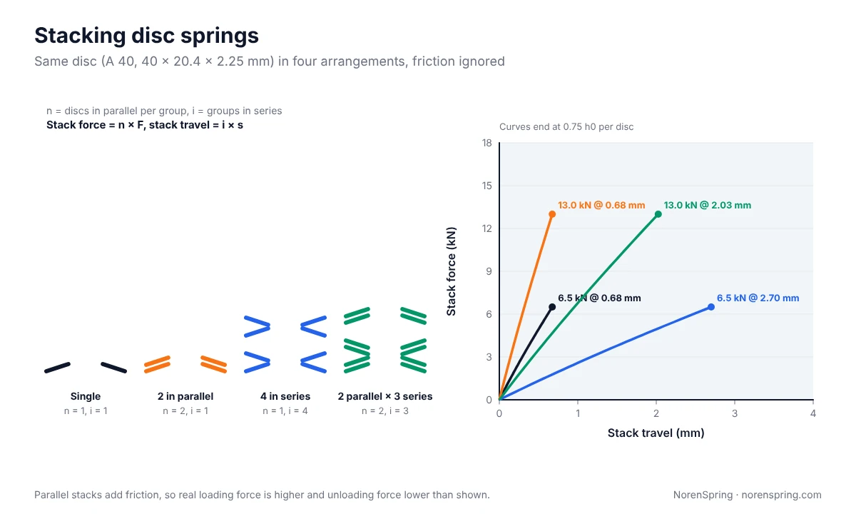
Stacking is how you turn a standard disc into the force and travel your design needs. The basic arrangements are:
- Parallel (nested, same direction). n discs nested together give about n times the force of one disc at the same travel. Two A 40 discs give 13 kN at 0.68 mm.
- Series (face to face, alternating). i discs placed face to face give i times the travel at the same force. Four A 40 discs give 6.5 kN over 2.7 mm.
- Combined. Groups of nested discs placed face to face. Two in parallel times three in series give 13 kN over 2.0 mm.
The free length of a stack of i groups, each with n nested discs, is i × [l0 + (n − 1) × t]. For the 2 × 3 stack of A 40 discs that is 3 × (3.15 + 2.25) = 16.2 mm.
You can also build progressive stacks. Mix groups of different sizes, for example one single disc followed by pairs and then triples. The singles flatten first, then the pairs, then the triples, so the stack gets stiffer as it compresses. This is useful for buffers that should be soft at first and firm at the end of the stroke.
Friction in parallel stacks
Nested discs slide against each other as they flatten. That friction makes the stack harder to compress and lets it push back with less force on the way out, so the loading and unloading curves form a loop. Some designs use the loop on purpose to damp vibration. Where you need an accurate force, keep nested groups small. Machine Design puts the practical limit at two to four discs in parallel. Lubricate the contact faces. Series stacks have much less friction because only the edges touch.
Guiding a stack
A stack of loose discs will slide sideways under load, so it needs a guide.
- Use an inner rod or an outer sleeve. For dynamic loads, harden and grind or polish the guide surface so the discs do not wear grooves into it. Machine Design specifies case hardening to 55 HRC for dynamic loads.
- Leave clearance. As a disc flattens, its outside diameter grows slightly and its inside diameter shrinks. A tight rod or sleeve causes binding and extra friction. The right clearance grows with disc size, from a few tenths of a millimetre on small discs to more than a millimetre on large ones, so take it from the standard or confirm it with your supplier.
- Keep the stack short. A widely used rule of thumb is that a stack should not be taller than three times the outside diameter. Longer stacks should be split into two or three partial stacks with guided washers between them.
- Use an even number of series groups. That way both end discs sit on their outside diameter, which spreads the load on the end plates.
- Make the end plates hard and flat. The edges of a disc spring dig into soft steel and the stack loses force.
Disc spring materials and finishes
Most disc springs are made from strip or plate spring steel, then formed, heat treated and preset. Presetting means pressing every disc flat once after hardening, which removes the initial set so the height stays stable in service. EN 16983 uses carbon spring steels such as C67S and C75S for thin discs. It uses the chromium–vanadium steel 51CrV4 for thicker discs, which is close to the Chinese grade 50CrVA. Where corrosion or temperature rules out carbon steel, makers turn to stainless grades such as 1.4310 (301) and 17-7 PH, or to nickel alloys. Stainless discs give less force and less fatigue margin than carbon-steel discs of the same size, so recalculate the load with the stainless modulus.
| Need | Common choice | Note |
|---|---|---|
| General machinery, indoors | Carbon or Cr-V spring steel, phosphate and oil | Lowest cost; oil film protects in storage |
| Outdoor or humid service | Spring steel with zinc flake (Dacromet), or zinc plating with hydrogen relief | Ask how hydrogen embrittlement is controlled |
| Corrosive media, food, marine | Stainless steel | Lower load than steel of the same size |
| High temperature | Heat-resistant steel or nickel alloy | Relaxation rises with temperature; give the working temperature |
Plating matters more for disc springs than for many other springs, because they are hard and highly stressed. Electroplated zinc can let hydrogen into the steel and cause delayed cracking. At NorenSpring, zinc-plated springs are always baked after plating to drive the hydrogen out. If your disc springs are dynamically loaded, ask your supplier whether a zinc flake coating or mechanical plating would be better than electroplating. Our guide to spring finishes and coatings compares zinc flake, plating and other options in more detail.
Shot peening blasts the surface with small steel shot and leaves a layer of compressive stress. That compressive layer slows crack growth at points II and III, so it is often specified for dynamically loaded disc springs.
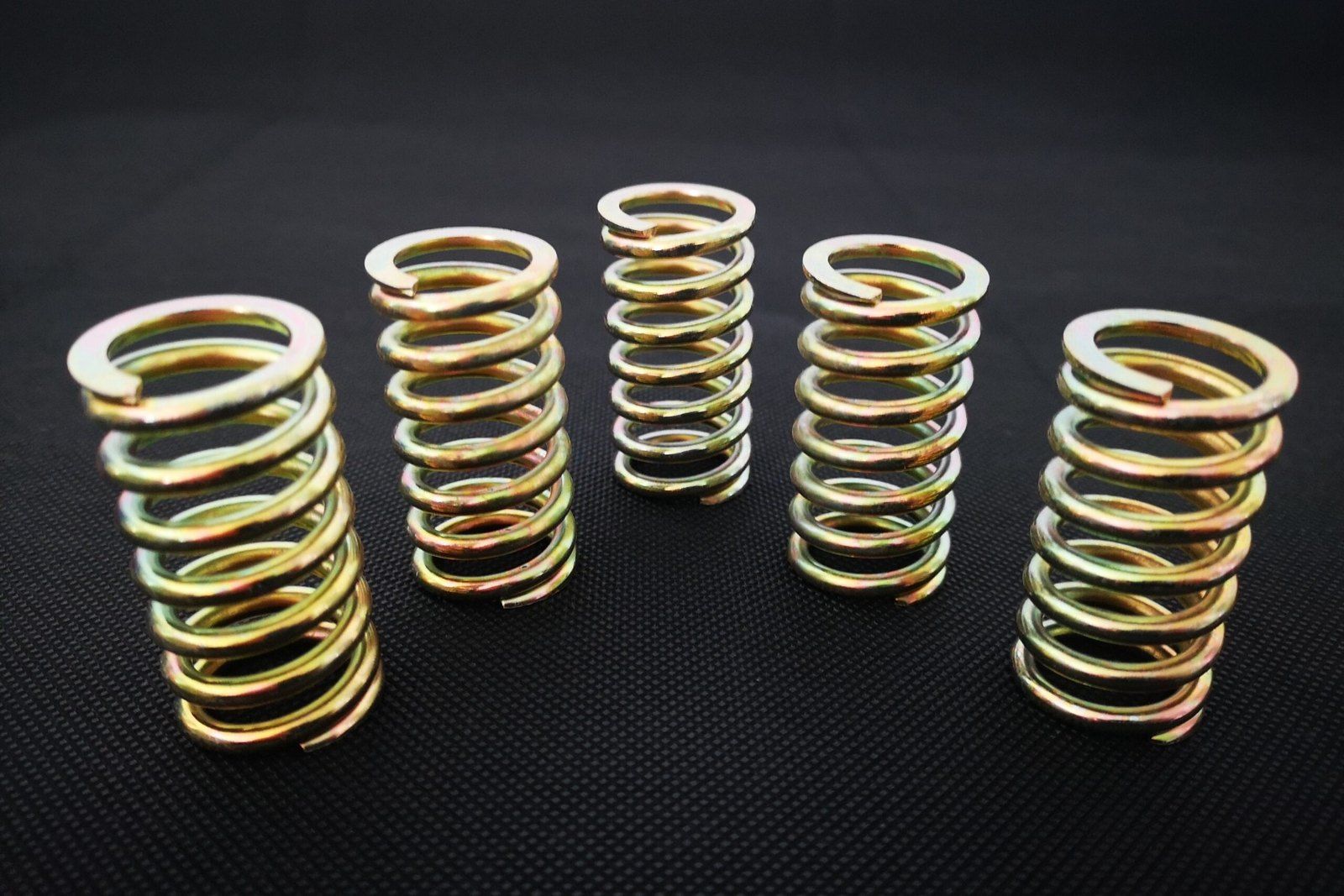
Disc springs from NorenSpring. We make disc springs to customer drawings in outside diameters from 6 to 250 mm, inside diameters from 3 to 127 mm and thicknesses from 0.2 to 14 mm, and develop special sizes for specific applications. Materials include 50CrVA, 51CrV4 (1.8159) and 60Si2MnA spring steels and SUS301, SUS304 and SUS316 stainless steels. Finishes include black oxide, phosphate, zinc plating, Dacromet (zinc flake) and nickel plating. Nearly all our disc springs are shot peened. We produce to GB/T 1972, or to DIN EN 16983 (formerly DIN 2093) when the customer drawing calls for it. See the disc spring product page for photos and a quote form.
Disc spring vs DIN 6796 conical spring washer vs wave spring
Disc springs, conical spring washers and wave springs get confused in catalogues, but they do different jobs.
| Disc spring (EN 16983) | Conical spring washer (DIN 6796) | Wave spring | |
|---|---|---|---|
| Main job | High force in short travel, alone or stacked | Keeping clamp load on a bolted joint | Light preload in very little axial space |
| Force level | High | High, sized to a bolt diameter | Low to medium |
| Stacking | Series, parallel or combined | Usually one per bolt | Usually used singly; a multi-turn wave spring replaces a stack |
| Load curve | Set by h0/t, from linear to flat | Sized to be pressed flat at full bolt preload | Close to linear |
| Typical use | Valves, tooling, clutches, buffers | Bolted joints that settle or see temperature change | Bearing preload, seals, compact assemblies |
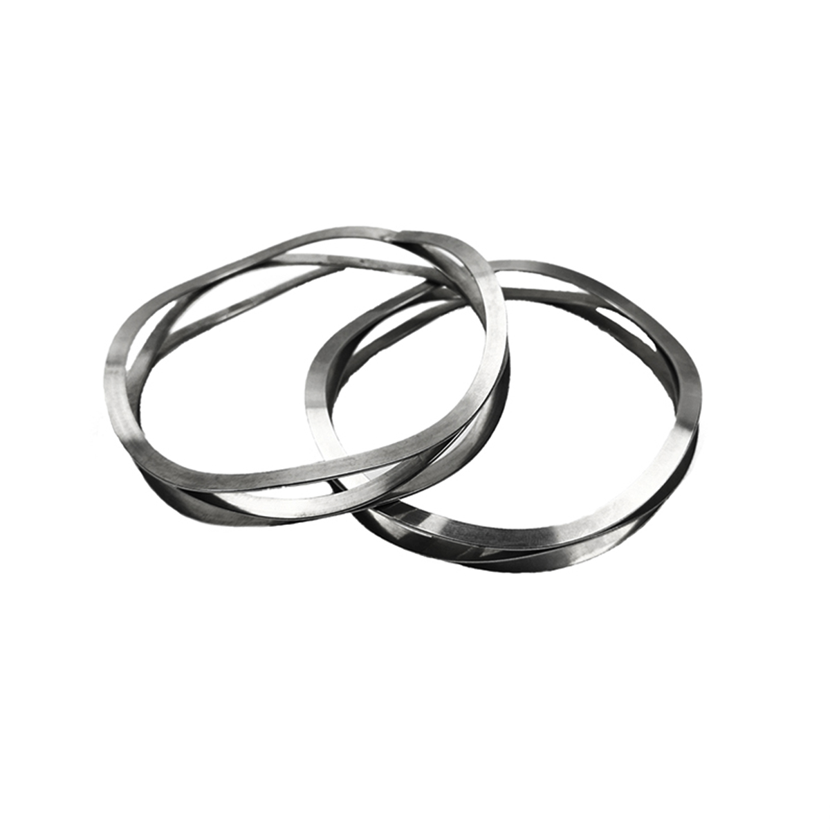
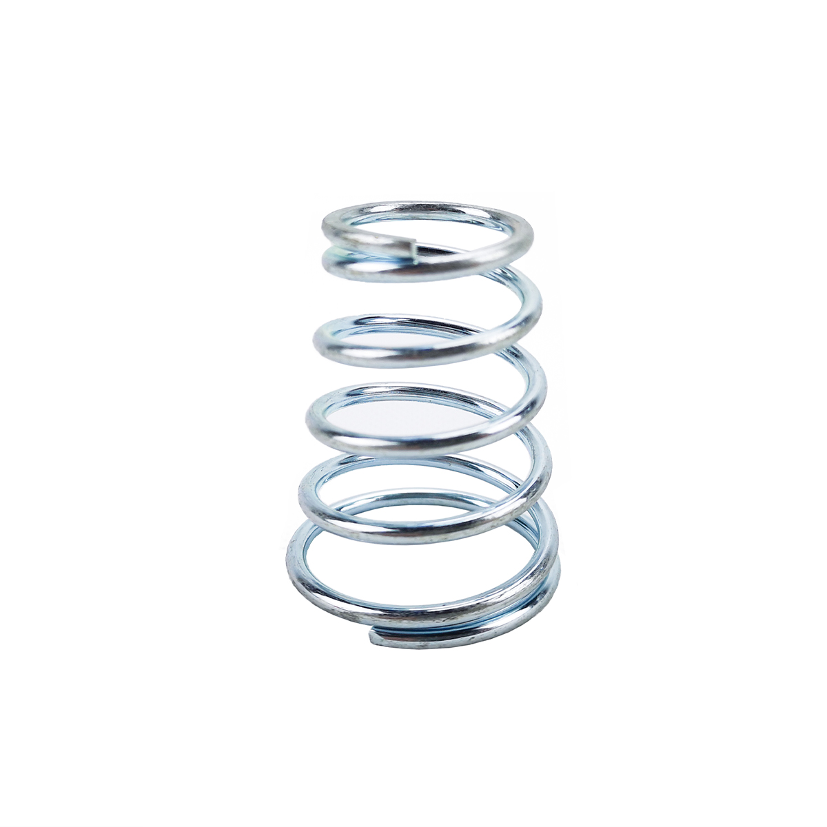
A DIN 6796 conical spring washer is a disc spring sized for a bolt. It keeps tension in a joint when gaskets creep or parts expand. On its own it does not lock a nut against vibration. A wave spring is a ring with waves formed into it. It gives less force than a disc spring of the same size but works in very little height. See our wave spring page for that option. For the numbers a maker needs and how each one changes the rate, see our guide to specifying a custom wave spring. A conical compression spring is a coiled spring with a tapered outline, and despite the similar name it is a different part.
Static vs dynamic loading and fatigue
How you check a disc spring depends on whether it is loaded once and held, or cycled.
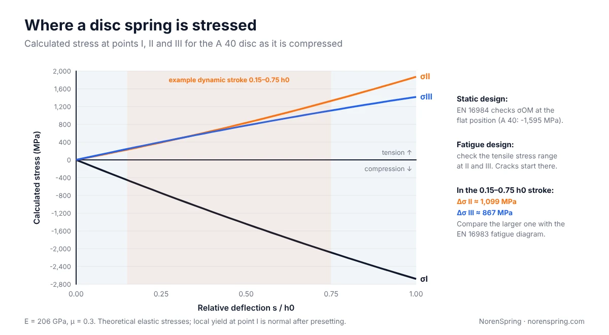
Static or rarely cycled loads. EN 16984 checks the calculated stress σOM at the flat position against the material’s strength. For the A 40 disc, σOM is about −1,595 MPa. Standard discs from the A, B and C series are designed to pass this check, so you can use them statically up to 75% of h0 without further calculation. The calculated stress at point I is higher still and can exceed the material’s yield strength. That is normal: presetting causes a small, intended local yield there.
Dynamic loads. Cracks in a cycled disc spring start on the underside, at point II or III, where the stress is tensile. To check fatigue, calculate the stress at both points at the preload and at the maximum deflection. Take the larger range and compare it with the fatigue diagrams in EN 16983. Those diagrams give allowable stress ranges for 100,000, 500,000 and 2,000,000 cycles, with separate charts for each thickness group.
To make a dynamically loaded stack last:
- Keep a preload. After presetting, point I holds residual tensile stress. A preload turns it into compressive stress and keeps the stack from rattling. A published fatigue example in Assembly magazine uses a preload of 15% of h0 and a maximum of 75%.
- Shorten the stroke where you can. The stress range, not the peak stress, drives fatigue. Moving the same stroke into more discs in series lowers the range in each disc.
- Avoid friction and wear. Lubricate, use a hardened guide, and keep parallel groups small. Worn guides and dry nested discs are common causes of early failure.
What to include in a disc spring RFQ
To get a price and a calculated load curve in our first reply, send the details below with your enquiry for custom disc springs. Our spring rate guide explains how to state force at a position, which works the same way for disc springs.
| Item | What to give | Example |
|---|---|---|
| Dimensions | De, Di, t, and h0 or l0, with tolerances | 40 × 20.4 × 2.25, l0 3.15 |
| Load | Force at a stated deflection or installed height | 6,500 N ±10% at 0.68 mm |
| Stack | Number of discs, n and i, guide type | 2 parallel × 3 series, inner rod Ø20 |
| Duty | Static, or dynamic with preload, stroke and cycles | 0.15 to 0.75 h0, 1 million cycles |
| Environment | Temperature, humidity, media | 80 °C, outdoor |
| Material and finish | Grade, coating, any standard to follow | 50CrVA, zinc flake, EN 16983 group 2 |
| Quantity | Prototype and annual volume | 200 pcs sample, 50,000 pcs/year |
If you only have an old part, send us a sample and tell us where it fits. We can measure it and propose a drawing. For more on stating forces at working positions, see our compression spring specification guide. Material grades are compared in the spring wire material guide.
Frequently asked questions
Is a disc spring the same as a Belleville washer?
Yes. Disc spring, Belleville washer, Belleville spring, disc washer and coned-disc spring all name the same cone-shaped spring. “Disc spring” is the term used in EN 16983 and EN 16984. “Belleville washer” is more common in North American catalogues and in bolted joint work.
Can a disc spring be pressed completely flat?
Most standard disc springs survive being pressed flat, and every disc is pressed flat once during presetting. In service, avoid it. Near flat the force climbs faster than calculated, the contact points move, and the stress is highest. Design the working point at or below 75% of h0.
How many disc springs can I stack?
Keep parallel groups to two to four discs, because friction grows with each added disc. In series, the limit is set by stability rather than a fixed count. Keep the stack no taller than about three times the outside diameter, and split longer stacks with guided intermediate washers.
Which way round do disc springs go in a stack?
In a series stack, discs alternate: inside edge to inside edge, then outside edge to outside edge. In a parallel group they nest in the same direction, like stacked paper cups. With an even number of series groups, both end discs bear on their outside diameter.
Are stainless steel Belleville washers as strong as carbon steel ones?
No. Stainless grades have a lower elastic modulus and lower strength, so a stainless disc of the same size gives less force and has less fatigue margin. Use stainless where corrosion requires it. Then check the load with the stainless modulus, or choose a thicker disc.
About the authors
This guide was prepared by the NorenSpring engineering team, which designs and manufactures custom compression, extension, torsion, disc and wave springs and wire forms in Xuzhou, China. Technical review by Feng Yulin, General Manager and senior structural engineer, who has 15 years of spring R&D experience and more than 30 national patents. NorenSpring holds IATF 16949, ISO 9001, ISO 13485, ISO 14001 and ISO 45001 certifications. More about NorenSpring.
All curves, stresses and worked numbers in this article were calculated by our team with the Almen–László equations and checked against the load values in EN 16983’s tables.
Sources
- DIN, DIN EN 16983, Disc springs: quality specifications and dimensions. Source for the A, B and C series, thickness groups, table loads at 0.75 h0 and fatigue diagrams. Retrieved 2026-10-08.
- Slovak Office of Standards, preview of EN 16983 and EN 16984, Disc springs: calculation. EN 16984 replaces DIN 2092 and holds the Almen–László design equations. Retrieved 2026-10-08.
- J. O. Almen and A. László, “The uniform-section disk spring”, Transactions of the ASME, vol. 58, 1936. Origin of the load and stress equations used here.
- Wikipedia, Belleville washer. Source for the 1867 patent and the three-times-OD stack height rule of thumb. Retrieved 2026-10-08.
- Machine Design, Bellevilles put the squeeze on. Source for guide rod hardness, even-numbered stacks and the two-to-four disc parallel limit. Retrieved 2026-10-08.
- Assembly magazine, How to calculate fatigue life of disc springs, September 2019. Source for the 15% preload example. Retrieved 2026-10-08.
- SAMR/SAC, GB/T 1972.1-2023, Disc springs, Part 1: Calculation (Chinese national standard).