

In this article
- Key takeaways
- What is a wave spring, and when does it beat a coil spring?
- Single-turn, multi-turn and nested wave springs: which type fits?
- When do you need a custom wave spring?
- What numbers does a wave spring manufacturer need?
- What sets the rate of a wave spring?
- Wave spring rate calculator: what happens if you change a dimension?
- Reading the load–deflection curve and choosing the working height
- Fit and clearance: why a wave spring grows in diameter
- Wave spring vs coil spring vs disc spring
- Materials and finishes
- What to send NorenSpring
- Frequently asked questions
- Summary: specify the load, then check the fit
- About the authors
- Sources
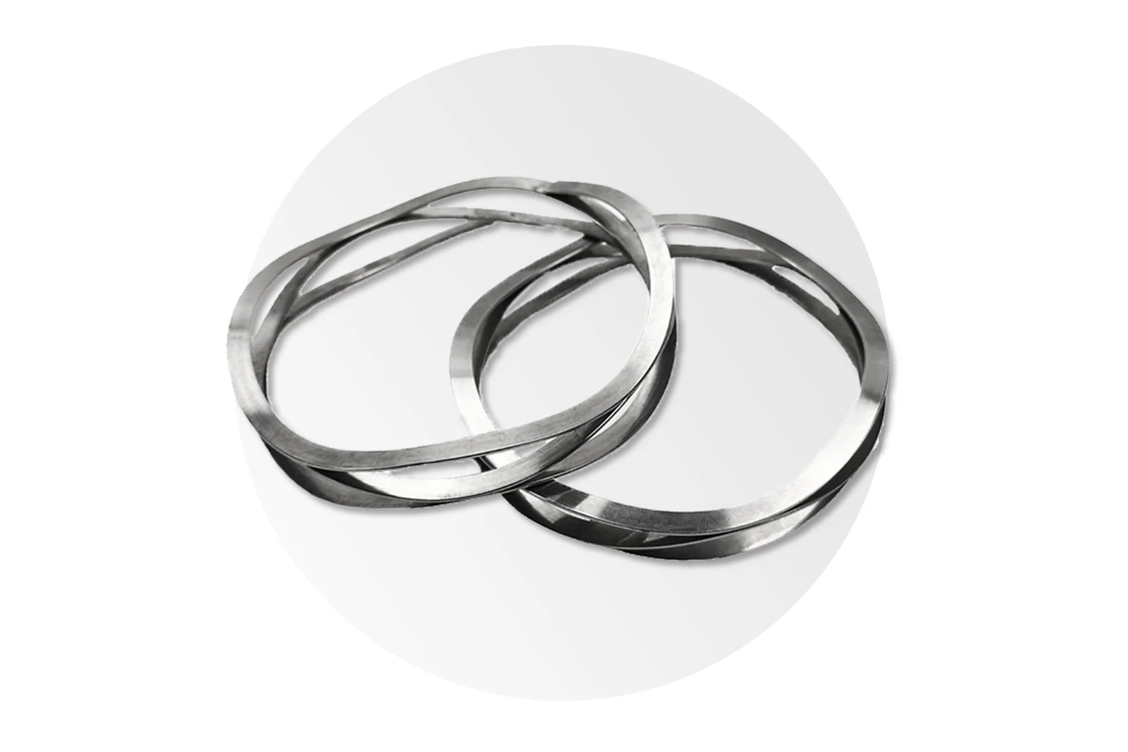
A wave spring is a ring of flat wire coiled on edge with waves formed in it, so it can give the same axial force as a round-wire coil spring in less height (makers report as little as half; see below). To get a custom wave spring made, a manufacturer needs four numbers: the bore, the shaft, the height the spring works at and the load it must give at that height. A maker can usually propose a design from those and then choose the free height, the waves, the turns and the strip size to fit.
The catch is that every dimension is linked: change the thickness, the number of waves or the number of turns, and the load moves in large steps. This guide explains the three types, when a custom spring is needed, the numbers to send with a request, what sets the rate, how to choose a working height, how the spring grows wider when it is compressed, and how a wave spring compares with coil and disc springs. A free relative rate calculator is included.
Key takeaways
- Give a load at a height. Bore, shaft, working height and the load at that height are enough to start. Let the maker choose waves, turns and strip size. Rotor Clip’s white paper gives the same design tip: always specify the load at work height [4].
- Waves and thickness drive the rate. Rate rises with the cube of thickness and roughly the fourth power of waves per turn. In the worked example below, half a wave more raises the rate by about 70%, and 10% more thickness raises it by about 33%.
- Turns trade force for travel. In a multi-turn spring the rate falls as one over the number of turns, and each extra turn adds height and travel.
- Work in the middle of the curve. Rotor Clip advises 20% to 80% of the travel for multi-turn springs and 30% to 70% for single-turn and nested springs [3].
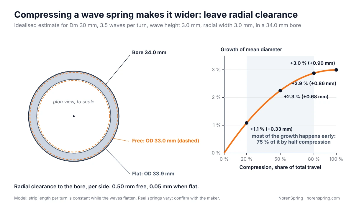
- Leave radial room. A compressed wave spring gets wider: in the worked example by about 0.7 to 0.9 mm (2% to 3%) when flat, and in the sine-wave model most of that happens in the first half of the travel. Check the clearance at the most compressed height.
What is a wave spring, and when does it beat a coil spring?
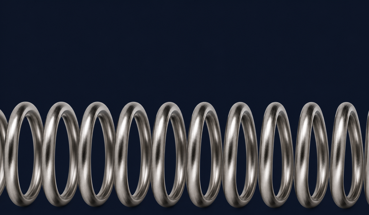
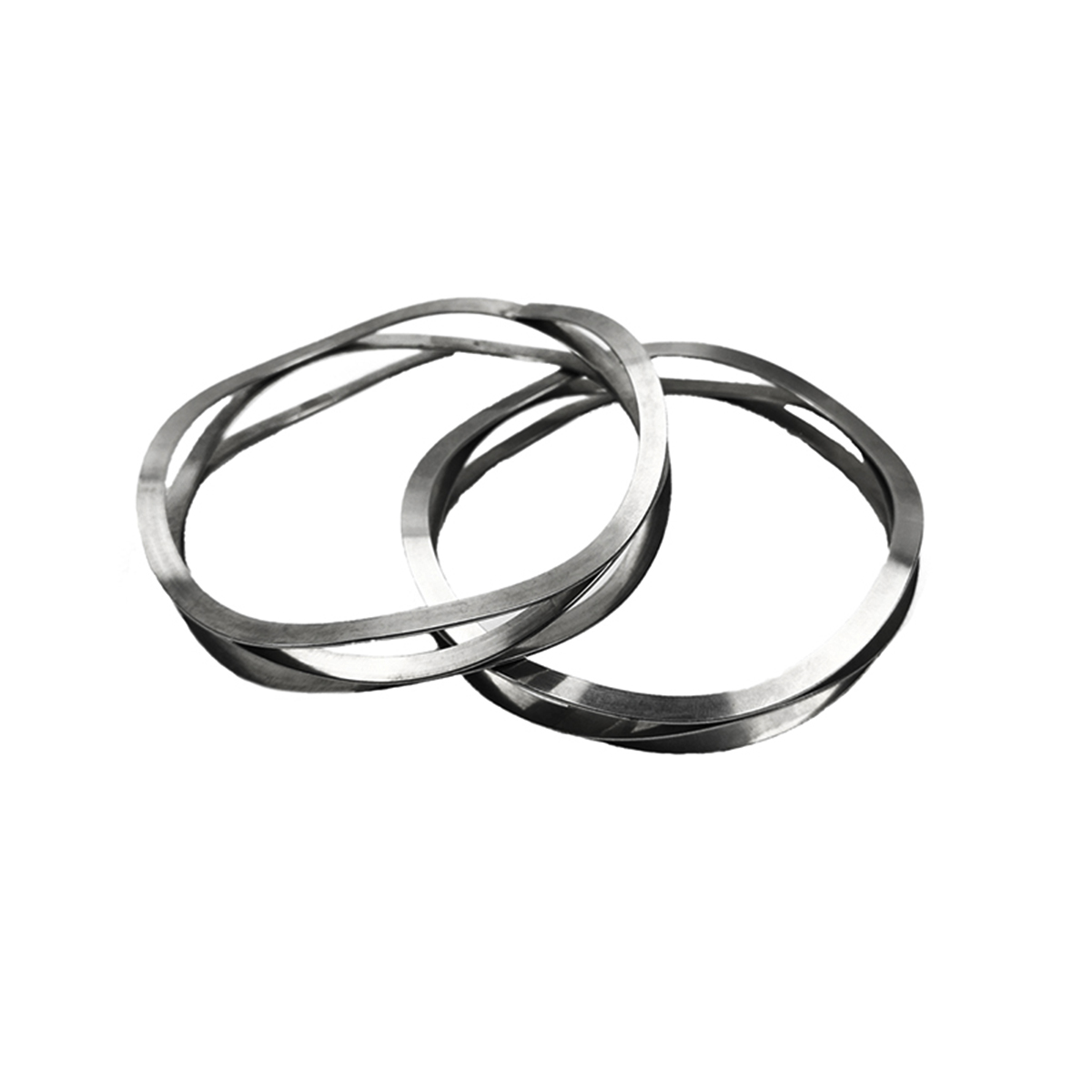
A wave spring beats a coil spring when travel is short to medium and height is tight, and a coil spring wins on long strokes. Flat wire, or strip, coiled on edge gives a ring with a wide, thin cross-section. Forming waves in it turns the ring into a spring: load it along its axis and the waves flatten, which stores energy. The Wikipedia article on wave springs describes the same three basic constructions covered in the next section [1].
The saving in height comes from the flat wire. A round-wire coil spring needs several coils, each at least one wire diameter tall, to give a useful travel. A wave spring packs the same deflection into the wave height of a thin strip. Rotor Clip says its wave springs take up to 50% less axial space than compression springs [2], and Smalley says its crest-to-crest springs can develop similar forces in one half or less of the axial space [6]. Treat both as best cases reported by makers, not guarantees. Rotor Clip’s white paper puts the saving at about 50% of the work height for static loads and about 30% for dynamic ones, because a spring that cycles needs more turns to keep bending stress down, and each turn adds height [4].
Our wave springs page lists valves, bearings, seals, electrical devices, automotive components and precision machinery among the typical wave spring applications. Rotor Clip’s white paper names bearing preload, connector and fluid power seals and mechanical seals, and says most applications need only short travel, usually under 1 mm, although it has built multi-turn springs with up to 50 mm of travel [4].
A wave spring does not always win:
- Long travel. A coil spring gives far more travel for the same force. If your design needs a long stroke, start with a coil spring and read our guide to specifying a custom compression spring.
- Very high force in a tiny travel. A disc spring is often the better fit. The comparison table later in this guide sets the three side by side.
- A drop-in swap. A wave spring is a ring that sits on a flat seat, in a bore or on a shaft. If the housing was cut for a coil spring, the seat and the guide usually change too.
Single-turn, multi-turn and nested wave springs: which type fits?
Choose by how far the spring must travel and how much force it must give in the height you have. Single-turn and nested springs suit short travel. Multi-turn springs suit more travel at a lower rate.
Single-turn wave springs
A single-turn spring is one turn of wave in a ring, and its ends are a gap or an overlap. Rotor Clip describes single-turn springs as ideal for tolerance take-up or preloading bearings [2]. Smalley lists them as low to medium force and low to medium rate, with short deflection [8].
Multi-turn (crest-to-crest) wave springs
A multi-turn spring is several turns stacked so that the crests of one turn rest against the next. It behaves like several single-turn springs in series. Smalley describes its crest-to-crest springs as pre-stacked in series, which lowers the rate by a factor tied to the number of turns [6]. Each added turn adds height and travel. Like every wave spring, a multi-turn spring grows wider as it compresses (see the fit section). Multi-turn springs come with plain ends or with shim ends. A shim end finishes the spring with a flat turn so it seats on a flat face instead of on the wave crests.
Nested wave springs
A nested spring is wound in layers, in parallel, so the layers nest and share the load. Rotor Clip describes nested springs as coiled in parallel to form a continuous coil of layers that raises load performance [2]. Smalley says nested springs are pre-stacked in parallel, which raises the rate by a factor related to the number of turns, and lists high force with short deflection [8]. A nested spring gives more force in nearly the same height as a single-turn spring, with short travel.
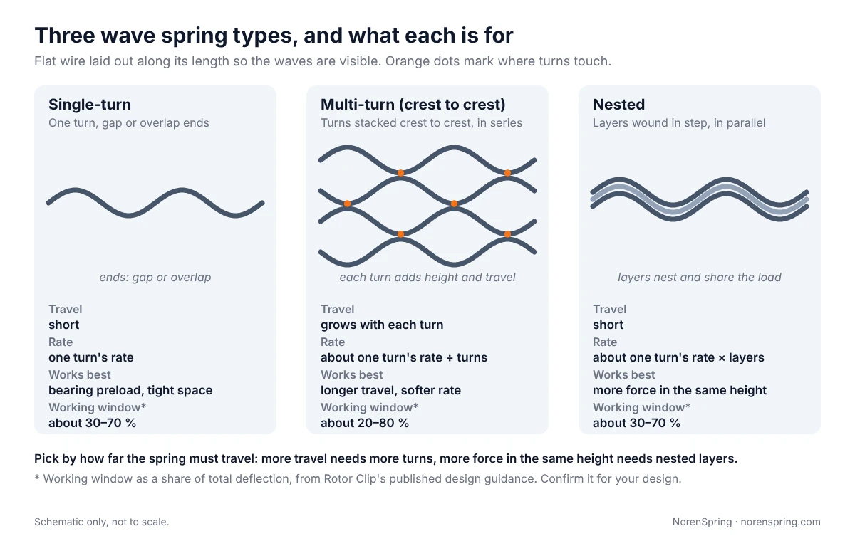
Rotor Clip’s design formulas page gives a working window as a share of the total travel. It advises keeping deflection between 20% and 80% for multi-turn springs and between 30% and 70% for single-turn and nested springs [3]. Outside that window the curve bends away from a straight line, as the load curve section below shows.
One more difference matters for tolerances. In a multi-turn spring, every turn contributes its own height variation to the free height, so it is reasonable to expect a tight free-height tolerance to be harder to hold on many turns than on one. Ask the maker what tolerance it can hold. That is one more reason to specify a load at a height and not a free height alone.
When do you need a custom wave spring?
If a catalogue wave spring gives your load at your working height and still clears your bore and shaft after it grows in compression, use it. Catalogue sizes are listed by bore, shaft, free height, work height and load [9], so you can check one against your numbers first. A custom wave spring makes sense when no stock size meets the bore, shaft, height and load together. The usual reasons are these:
- Your bore and shaft fall between catalogue steps. In the fit example below, a spring with a 33.0 mm outside diameter in a 34.0 mm bore keeps as little as 0.05 mm per side when flat, so a small change in diameter decides whether a stock size fits.
- Your load falls between the steps. Half a wave more raises the rate by about 70% and 10% more thickness by about 33% (see the rate section), so a catalogue series can jump over the load you need.
- The duty needs more turns. A spring that cycles needs a lower stress than one that is squeezed once, which usually means more turns and more height [4]. A stock series may not offer that combination in your bore.
- The material or end form is not stocked in your size. Smalley’s stock part page CS075-M2 offers carbon steel and 17-7 stainless steel [9]. A different grade, a nickel alloy, or a shim-end version in a size the catalogue does not list usually means a custom part.
- You need more force in the same height. That points to a nested design, or to a thicker strip with more waves.
If none of these applies, a catalogue spring is the faster route.
What numbers does a wave spring manufacturer need?
A wave spring manufacturer needs four numbers to propose a design:
- Bore diameter.
- Shaft diameter, if there is one.
- Working (installed) height.
- Load at the working height, with a tolerance.
Add the duty, the temperature, the medium and the quantity, and the maker can quote. The table shows what each number fixes.
| You give us | Typically worked out from it | Why it matters |
|---|---|---|
| Bore diameter, and shaft diameter if there is one | Outside diameter, inside diameter, radial width of the strip | The spring must clear the bore after it grows wider in compression, and stay guided on the shaft |
| Working height (installed height) | Free height, number of turns | The load is set at the installed height, not at the free height |
| Load at the working height, with a tolerance | Strip thickness, waves per turn, number of turns | This is the main performance requirement |
| A second point: load at another height (for example a preload), or the rate | Slope of the curve | Two points fix both the slope and the position of the curve |
| Space limits: maximum free height and seat details (flat or shim end, rotating or sliding contact) | Type and end form | Maximum free height is a space limit, not a target |
| Duty: static, occasional or cycling, and how fast | Stress level, turns, material | A spring that cycles needs lower stress, which usually means more turns |
| Temperature and medium (oil, water, air, chemicals) | Material and finish | Corrosion and heat change the material choice |
| Quantity: prototypes and yearly volume | Process route | A prototype and a production run are not always made the same way |
| Drawing, sketch or sample | Feasibility check | We accept DWG, DXF, STEP, PDF, JPG and PNG |
A request that gives a maker enough to start might read like this. The numbers are illustrative.
- Bore 40.0 mm, shaft 30.0 mm
- 125 N ± 10% at a working height of 5.0 mm
- Preload of 50 N at 8.0 mm
- Steady load with a few thousand cycles, 80 °C, light oil
- 5,000 pieces a year, prototypes first
Fix the load, not every dimension. Wave springs are normally specified by the load at a working height. If the drawing also fixes the free height, the thickness and the wave count tightly, the maker has nothing left to adjust to reach your load. List free height as a reference value. The same logic applies to coil springs, where two forces at two lengths fix the curve and leave the maker free to set the rest. Rotor Clip’s white paper makes this a design tip: always specify the load at work height [4]. Our spring rate guide explains that approach in detail.
What sets the rate of a wave spring?
Strip thickness and waves per turn matter most: the rate rises with the cube of the thickness and roughly the fourth power of the waves per turn. For a multi-turn (crest-to-crest) wave spring in a given material, the rate, which is the load per millimetre of deflection, scales like this:
rate ∝ b · t³ · N⁴ · (OD ÷ ID) / (Dm³ · Z)
Here b is the radial width of the strip, t its thickness, N the number of waves per turn, Dm the mean diameter, Z the number of turns, and OD ÷ ID the ratio of outside to inside diameter, which is (Dm + b) ÷ (Dm − b). For a nested spring the rate rises with the number of layers instead of falling with turns. Rotor Clip’s own page uses different letters: N for turns, Z for waves per turn, T for thickness and SW for radial width. Check the definitions before you compare formulas.
This is Rotor Clip’s published multi-turn deflection formula [3] turned around to give the rate, with two terms left out of the proportion: the modulus E, which is fixed for a given material, and a wave factor K, which depends on the number of waves per turn and is held constant here. K sits in the denominator of the rate, so a lower K means a stiffer spring. Rotor Clip’s formulas page lists these values [3]:
| Waves per turn | Wave factor K |
|---|---|
| 2 to 4 | 3.88 |
| 4.5 to 6.5 | 2.90 |
| 7 to 9.5 | 2.30 |
| 10 or more | 2.13 |
We show only proportions. The absolute rate also depends on K, on the wave form and on the ends, so use the proportions to compare designs and ask the maker for the real value.
The powers also follow from beam bending. Each wave works like a small beam. Standard beam-deflection tables [11] show that a beam’s stiffness rises with the cube of its thickness and falls with the cube of its length. More waves per turn means shorter beams, which are much stiffer, and the load is shared among more of them. Together those effects give the fourth power of N. Each extra turn adds another spring in series, so the rate falls as one over the number of turns [6]. The OD ÷ ID term comes from Rotor Clip’s formula [3] and not from this simple argument. It moves the result by only about 2% for a 10% change in radial width or diameter.
Take a spring with a radial width of 3.0 mm, a thickness of 0.30 mm, 3.5 waves per turn, a mean diameter of 30 mm and 3 turns. Change one thing at a time:
- Half a wave more (3.5 to 4.0): rate × 1.71.
- Half a wave fewer (3.5 to 3.0): rate × 0.54.
- Strip 10% thicker (0.30 to 0.33 mm): rate × 1.33.
- One more turn (3 to 4): rate × 0.75.
- Mean diameter 10% larger (30 to 33 mm): rate × 0.74.
- Radial width 10% larger (3.0 to 3.3 mm): rate × 1.12.
The two wave-count steps stay inside the 2 to 4 wave band, where K does not change. A step across a band, such as 4.0 to 4.5 waves, lowers K and raises the rate by more than the fourth-power rule alone gives.
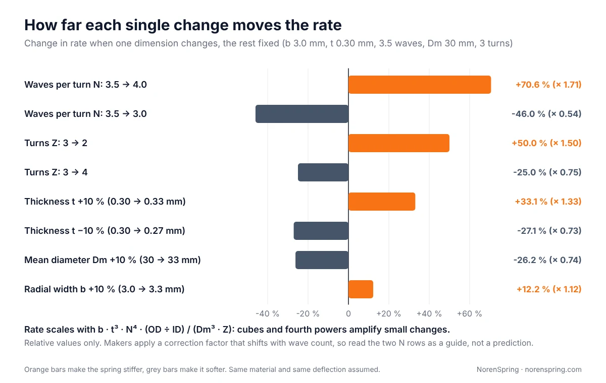
Three practical points follow:
- Thickness matters a lot. Every 1% of strip thickness moves the rate by about 3%. In practice a maker trims the design, through thickness, waves or turns, to reach your load. That works better than building to a fixed set of nominal dimensions.
- A turn is a gentle step, a wave is a big one. Adding a turn is the gentle way to soften a spring, at the cost of height. Waves per turn come in discrete steps, and catalogue sizes list values such as 3.5, so the steps are coarse.
- A larger diameter softens the spring. A design that moves to a bigger bore needs a thicker strip or more waves to hold the same load.
Wave spring rate calculator: what happens if you change a dimension?
The calculator below compares two designs. Enter your current wave spring and a changed version. It shows how many times stiffer or softer the new one is at the same deflection. It does not give an absolute rate. It is meant for early comparisons, such as “what if we move up half a wave” or “what if the mean diameter grows by 2 mm”. If you already know the load of your current spring, the optional load box scales it to the new design at the same deflection. Confirm any change with a sample or a test.
Wave spring relative rate calculator
Enter your current wave spring and a changed design. The calculator shows how many times stiffer or softer the new one is, and can scale a load you already know.
Relative rate = (b₂ ÷ b₁) · (t₂ ÷ t₁)³ · (N₂ ÷ N₁)⁴ · (Dm₁ ÷ Dm₂)³ · (Z₁ ÷ Z₂) · [(OD₂ ÷ ID₂) ÷ (OD₁ ÷ ID₁)], with OD = Dm + b and ID = Dm − b, same material, compared at the same deflection, for multi-turn crest-to-crest springs. For nested springs the rate rises with the number of layers instead. It shows direction and size of a change, not an absolute rate. The optional load box scales your load at the same deflection in mm, assuming the straight part of the curve. It is not the load at a new working height. Makers apply a wave factor K that changes with wave count, so the wave-count result is least exact. Confirm any change with a sample or a test.
Reading the load–deflection curve and choosing the working height
Put the working height in the middle of the curve and away from flat. A wave spring's load curve usually has three parts, as the schematic in Figure 3 shows. At the start, the load rises slowly while the spring seats and friction settles. Through the middle, the load follows an almost straight line. Near flat, the waves have almost gone, the strip begins to act as a solid ring and the load climbs steeply. Rotor Clip says wave springs keep a relatively linear rate over a broad deflection range [5], and its white paper puts the linear region at 30% to 70% deflection [4].
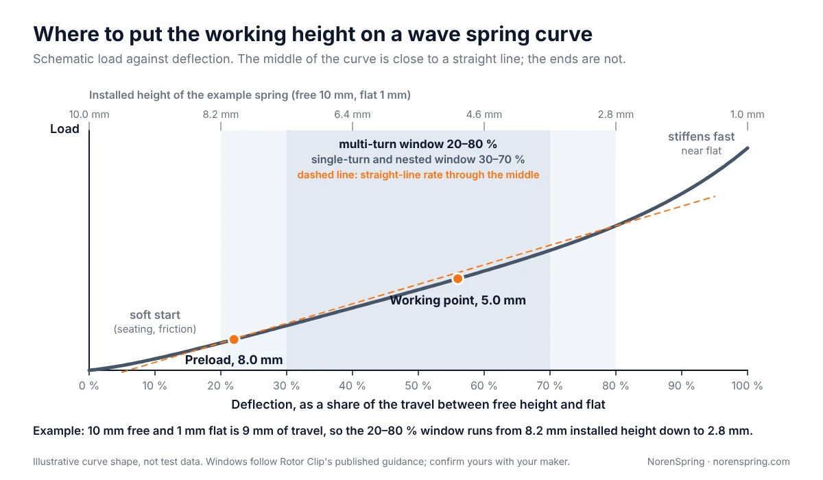
Use two points to describe your need, usually a preload and a working load. In the example in Figure 3, the spring is 10 mm free and 1 mm flat. It has 9 mm of travel, so the 20% to 80% window runs from an installed height of 8.2 mm down to 2.8 mm. A preload at 8.0 mm and a working point at 5.0 mm both sit inside it. The example is a multi-turn spring, so the wider window applies.
The request above implies a rate of about 25 N/mm in the middle of the curve: (125 − 50) N over 3.0 mm. A straight line through the two points reaches zero load at about 10 mm, close to the free height of the spring in Figure 3, so this is that spring and not the spring in Figures 2 and 4. The preload at 8.0 mm is at 22% of the travel, inside the 20% to 80% window but below the 30% to 70% region that Rotor Clip's white paper calls linear [4], so treat 25 N/mm as an estimate.
Height tolerance turns directly into load tolerance. At 25 N/mm, a housing depth that varies by ±0.1 mm moves the load by ±2.5 N. On a 125 N working load that is ±2%. On a 50 N preload at 8.0 mm it is ±5%. The lowest load in the design is the one most sensitive to the housing in percentage terms. If both points matter, tell the maker what tolerance your housing can hold.
Check the stress as well. Rotor Clip says the stress should never exceed the minimum tensile strength of the flat wire, and it ties fatigue life to the ratio between the two work heights [3]. That is an upper limit, not a design target. A spring that cycles needs a lower stress than one that is only squeezed once.
Friction between turns adds some hysteresis, so the loading and unloading curves differ slightly. State on the drawing which direction the load is measured in, usually while compressing. Never use the flat position as a working position.
Fit and clearance: why a wave spring grows in diameter
A wave spring gets wider when it is compressed, so leave radial clearance. Smalley says the diameter of a wave spring grows as it is compressed, and that crest-to-crest and nested springs bind if the outside diameter touches the bore. Smalley adds that a gap or overlap spring can grow without binding because of its gap or overlapping ends [7]. The cause is simple. The strip keeps the same length while the waves flatten. A wavy strip is longer than the flat circle beneath it, so as the waves flatten that extra length has to go somewhere, and it goes into a larger diameter.
Two simple models put a number on the effect. Ours assumes sinusoidal waves, a closed ring whose ends take up no length, constant strip length per turn, and a wave height that falls in step with the compression. To a first approximation, the share by which the mean diameter grows when the spring is flat is (N · a / Dm)², where N is the number of waves per turn, a is the half wave height and Dm is the mean diameter. In millimetres that is (N · a)² ÷ Dm. The second is a formula on Rotor Clip's formulas page, shown there as an image, which gives the compressed diameter from the free diameter, the waves per turn, and the free and work height of each turn [3]. It treats each quarter wave as a straight segment.
Take a spring with a 30 mm mean diameter, 3.5 waves per turn, a wave height of 3.0 mm (so a = 1.5 mm) and a radial width of 3.0 mm. The approximation gives (3.5 × 1.5 ÷ 30)² = 3.1%, and a numerical integration of the strip length gives 3.0%, or 0.9 mm [12]. For Rotor Clip's formula we use the free outside diameter, 33.0 mm (mean diameter plus radial width), a free height of 3.0 mm per turn and a work height of 0.3 mm, the strip thickness. The table compares the two in a 34.0 mm bore.
| Model | Growth when flat | Outside diameter when flat | Clearance per side (0.50 mm when free) |
|---|---|---|---|
| Sine wave, numerical integration [12] | 0.90 mm (3.0% of Dm) | 33.90 mm | 0.05 mm |
| Straight segments, Rotor Clip formula [3] | 0.66 mm (2.0% of OD) | 33.66 mm | 0.17 mm |
The models differ mainly because a straight-segment wave has a shorter strip path than a sine wave of the same height. They also start from different diameters, the outside diameter for Rotor Clip's formula and the mean diameter for ours. Counting the strip thickness in the free height per turn (3.3 mm) moves the straight-segment result to 33.80 mm, or 0.80 mm. Real wave forms differ from both, so ask the maker for the real value.
For a first clearance check, use the larger growth. To keep 0.25 mm per side when flat, this spring needs a bore of at least 34.4 mm. In the sine-wave model the inside diameter grows by the same amount as the outside diameter. For the same waves and wave height, a larger diameter grows by a smaller share, so do not treat 3% as a rule.
Three consequences follow:
- Check clearance at the most compressed height, not the installed height. The growth is not linear. In the sine-wave model, 75% of it has happened by half compression, because it follows the square of the wave height. Check the compressed outside diameter against the bore.
- Tell the maker what guides the spring. A spring in a bore is guided by its outside diameter, and a spring on a shaft by its inside diameter. Many designs have both. The inside diameter grows too, so the gap to the shaft widens: with a 26.0 mm shaft and a free inside diameter of 27.0 mm, the gap per side goes from 0.50 mm to about 0.95 mm when flat in the sine-wave model. Check the guiding gap at the free height and at the most compressed height. For scale only, Smalley's gap-type single-turn example leaves 0.020 in (0.5 mm) per side in the bore and 0.010 in (0.25 mm) per side over the shaft [8].
- Describe the seat. A plain end touches the seat at the wave crests, and a shim end gives a flat face. A seat that is not square to the axis loads one side more than the other. If the spring turns with a shaft or slides against a seat, tell the maker. The friction affects the curve and the wear.
These numbers come from a simplified model. Real springs depend on the wave form and the ends, so ask your maker to check a critical fit.
Wave spring vs coil spring vs disc spring
Choose a wave spring for moderate loads in a flat space, a coil spring for long strokes, and a disc spring for high loads over short strokes.
| Property | Wave spring | Coil (compression) spring | Disc spring |
|---|---|---|---|
| Best at | Short to medium travel in a flat package | Long travel, wide range of loads | Very high force over very short travel |
| Height for the same force | Small. Rotor Clip reports up to 50% less axial space than compression springs [2], Smalley half or less [6] | Tallest. Solid height is several wire diameters | Short for one disc, taller when stacked |
| Load curve | Nearly linear in the middle, steep near flat | Straight line, constant rate | Set by h0/t (cone height ÷ thickness): near-linear at about 0.4, flat at about 1.3, falling above about 1.41 (disc guide) |
| More travel | More turns in series | More coils | More discs face to face |
| More force | Nested layers, thicker strip, more waves | Thicker wire, fewer coils | More discs nested in parallel |
| Space and seat | Thin ring on a flat seat, bore or shaft guided | Round coil, bore or rod guided | Ring on a rod or in a sleeve |
If the force you need is very high and the travel short, read our disc spring guide, which covers stacking and a stack calculator. If you need a long stroke, start from a coil spring.
Materials and finishes
The environment decides the material. A spring in dry air and light duty can use carbon spring steel. A spring in damp air, water or mild chemicals usually calls for stainless steel, or coated carbon steel for light exposure. Higher temperatures and aggressive chemicals call for nickel or cobalt alloys.
- Carbon spring steel. Smalley's stock part page CS075-M2 offers SAE 1070-1090 carbon steel as one choice [9]. It needs a coating or oil film in damp conditions.
- Stainless steel. Austenitic grades such as 301, 304 and 316 resist corrosion, and ASTM A666 covers them as strip. A precipitation-hardening grade such as 17-7 PH gives higher strength, and the same Smalley part page offers 17-7 stainless steel as its stainless choice [9].
- Nickel and cobalt alloys. Rotor Clip lists Inconel, Elgiloy and Hastelloy among its materials, next to stainless steel [2].
Strip material is specified by standards such as ASTM A684 for high-carbon steel strip, ASTM A666 for austenitic stainless strip and ASTM A693 for precipitation-hardening stainless strip [10]. Ask the maker which specification and temper they use. Material also changes the rate, because modulus enters it directly. A spring in austenitic stainless steel is slightly softer than the same geometry in carbon steel, and the maker adjusts thickness or turns to restore the load. Temperature lowers both strength and modulus, so tell the maker the operating temperature. Our spring wire material guide compares round-wire grades and gives Chinese, Japanese, European and US equivalents. The strip standards above cover flat stock.
For finishes, tell us the one you need and our engineers will confirm what is available for wave springs. If you need zinc plating on high-strength spring steel, ask for baking after plating to relieve hydrogen embrittlement, and state the plating standard on the drawing. ASTM B850 is a guide to these post-coating treatments [10].
What to send NorenSpring
Send what you have, even if it is only a sketch. A short exchange with an engineer usually shows what is missing. The table above lists what each number fixes, and the request example shows the level of detail that is enough to start.
- Files. DWG, DXF, STEP, PDF, JPG or PNG. If you only have a sample, send it with a photo and tell us what it does.
- Reply. Our team will contact you within 24 hours (one business day) and tell you what else it needs.
- Quantity. There is no fixed MOQ. Quantities are evaluated by spring type, tooling and material requirements.
You can reach our engineers through the contact page, or see our manufacturing capabilities.
Frequently asked questions
What is a wave spring used for?
A wave spring applies a light to moderate axial force in a short space. Rotor Clip names bearing preload and tolerance take-up [2] and seals [4]. Our wave springs page also lists valves, electrical devices, automotive components and precision machinery. The flat package is the reason: the same force needs less height than a coil spring. That short-height preload is one reason wave springs appear in aircraft equipment; see our page on springs for aerospace equipment.
What is a crest-to-crest wave spring?
Crest to crest describes a multi-turn wave spring: several turns of waved flat wire stacked in series so the crests of one turn rest against the next. It gives more travel at a lower rate than a single-turn spring, in a compact height.
What is the difference between a wave spring and a wave washer?
A wave washer is typically stamped from sheet. A wave spring is coiled from flat wire, so the number of turns, the waves and the sizes can be chosen. Rotor Clip says its wave springs offer tolerances up to 50% tighter than stamped wave washers [5].
Can a wave spring replace a coil spring?
Often, if the housing can change. A wave spring can give the same load in a shorter height, so a design that is tight on height can gain room. It needs a flat seat and a bore or shaft to guide it, and it does not suit long strokes. Send us the current spring's load, height and travel, and an engineer can say whether a wave spring fits.
How much can a wave spring be compressed?
Rotor Clip advises keeping deflection between 20% and 80% of the travel between free height and flat for multi-turn springs, and between 30% and 70% for single-turn and nested springs [3]. Do not use the flat position as a working position.
Can I start a wave spring request without a drawing?
Yes. Send the bore, the shaft, the working height and the load at that height, plus the temperature and the quantity, or send a sketch or a sample with a photo. Our team will tell you what else it needs.
Summary: specify the load, then check the fit
A custom wave spring is specified by what it must do, not by how it is built: the bore and shaft it fits, the height it works at and the load it gives there. Waves, turns and thickness are the maker's levers, and they move the load in large steps. Work in the middle of the curve, leave radial room for the growth in compression, and tell the maker what the spring will touch. Send us your numbers or a sketch through the contact page.
About the authors
This guide was prepared by the NorenSpring engineering team, which designs and manufactures custom springs and wire forms in Xuzhou, China. Technical review by Feng Yulin, General Manager and senior structural engineer, who has 15 years of spring R&D experience and more than 30 national patents. NorenSpring holds IATF 16949, ISO 9001, ISO 13485, ISO 14001 and ISO 45001 certifications. More about NorenSpring. Figures and calculations were last checked on 10 October 2026.
Sources
Manufacturer pages are cited by title and retrieval date. The numbers in square brackets in the text refer to this list.
- Wikipedia, Wave spring. Source for the single-turn (gap and overlap), multi-turn and nested constructions. Retrieved 2026-10-10.
- Rotor Clip, "Wave Springs" (product overview page and its FAQ). Source for up to 50% less axial space, single-turn springs as ideal for tolerance take-up or preloading bearings, nested springs coiled in parallel as layers, up to 50% tighter force tolerances than wave washers, and the material list including Inconel, Elgiloy and Hastelloy. Retrieved 2026-10-10.
- Rotor Clip, "Formulas: Wave Springs". Source for the 20% to 80% and 30% to 70% deflection windows, the wave factor K values and variable names, the multi-turn deflection formula with its OD ÷ ID term, the stress limit, the link between fatigue life and the ratio of work heights, and the diametric expansion formula. Retrieved 2026-10-10.
- Rotor Clip white paper, "The Best Springs You Haven't Tried Yet". Source for about 50% of the work height in static use and about 30% in dynamic use, the extra turns needed to limit bending stress, the linear region at 30% to 70% deflection, bearing preload and seal applications, short typical travel and the design tip to specify the load at work height. Retrieved 2026-10-10.
- Rotor Clip, "Understanding the Differences Between Wave Washers and Wave Springs". Source for tolerances up to 50% tighter than stamped wave washers, the relatively linear rate over a broad deflection range, and the stamped construction of wave washers. Retrieved 2026-10-10.
- Smalley, "Crest-to-Crest® Wave Springs" product page and "Multiple Turn" design page. Source for similar force in half the axial space or less, and springs pre-stacked in series with the rate decreasing by a factor related to the number of turns. Retrieved 2026-10-10.
- Smalley, "Ask the Expert: Wave Spring Compression and Load" (2018-11-27). Source for diameter growth under compression, binding of crest-to-crest and nested springs at the bore, and gap and overlap springs growing without binding. Retrieved 2026-10-10.
- Smalley, "Single-Turn Wave Springs" product page, and the single-turn and nested pages of its spring design introduction. Source for low to medium force and short deflection of single-turn springs, nested springs pre-stacked in parallel, and the gap-type example of 0.020 in loose per side in the bore with 0.010 in per side over the shaft. Retrieved 2026-10-10.
- Smalley online catalogue, stock crest-to-crest part page CS075-M2. Source for the material choices Carbon Steel SAE 1070-1090 and 17-7 Stainless Steel, a part with 3.5 waves per turn, and the catalogue fields of bore, shaft, load, work height, free height and waves per turn. Retrieved 2026-10-10.
- ASTM International, A684/A684M, A666/A666M and A693, standard specifications for high-carbon steel strip, austenitic stainless strip and precipitation-hardening stainless strip, and B850, a guide to post-coating treatments of steel for reducing the risk of hydrogen embrittlement. Retrieved 2026-10-10.
- R. G. Budynas and J. K. Nisbett, Shigley's Mechanical Engineering Design, 11th edition, McGraw-Hill, 2020, appendix tables of beam deflections. Basis for the scaling of beam stiffness with thickness and length.
- NorenSpring engineering team, idealised calculations for Figures 2 and 4 and the calculator, 2026-10-10. Relative rate from Rotor Clip's multi-turn deflection formula turned around, with K held constant, and cross-checked against beam-bending scaling. Diameter growth from constant strip length per turn for a sine wave: first-order estimate (N · a / Dm)², checked by numerical integration of the strip length, and compared with Rotor Clip's straight-segment formula.