

In this article
- Key takeaways
- What you need before you start
- Spring dimensions: the five measurements every spring needs
- How to measure wire diameter
- How to measure a compression spring
- How to measure an extension spring
- How to measure a torsion spring
- How to count coils correctly
- Measuring load and rate
- Standards behind spring measurement
- Common measuring mistakes
- Spring measurement sheet for your RFQ
- Have a spring to match?
- Frequently asked questions
- About the authors
- Sources
How to measure a spring comes down to five things, recorded with the spring free, clean and unloaded: the wire diameter, the outside diameter, the free length, the total number of coils and the direction of wind. Use a micrometer for the wire and a caliper for the diameters and lengths. Then add the measurements that belong to the spring type: end type and solid height for a compression spring, length inside the hooks and hook position for an extension spring, and free angle and leg lengths for a torsion spring. If you can, measure the force at one or two lengths as well.
It is a common situation in maintenance and purchasing: there is an old spring from a machine, no drawing, and a new one has to fit and work the same. This guide shows how to take those measurements on industrial and equipment springs, which mistakes cause the most trouble, and how to put the results into a measurement sheet a manufacturer can quote from. Our three specification guides cover what to send for a custom compression spring, extension spring and torsion spring. This guide covers how to get those numbers from a spring in your hand.
Key takeaways
- Measure the free spring. Take every dimension with the spring out of the assembly, unloaded and clean. A spring measured while installed, stretched or wound up gives the wrong free length or free angle.
- Use a micrometer for the wire. Rate rises with the fourth power of wire diameter, so a wire that is 5% thicker gives a spring about 22% stiffer. A caliper is fine for diameters and lengths, but not precise enough for small wire.
- Measure extension springs inside the hooks. The length that matters is where the pins sit, not the body length or the overall length.
- Record the wind direction. Hold the spring with its axis vertical. If the coils facing you rise to the right, it is right hand; if they rise to the left, it is left hand. On torsion springs this is not optional.
- Measure force if you can. Two loads at two lengths, or two torques at two angles, define the spring better than any set of dimensions. If you cannot, give the installed length and working travel.
What you need before you start
You can take the basic measurements with ordinary workshop tools. The more precise the tool, the closer the copy.
| Tool | Use it for | Notes |
|---|---|---|
| Digital caliper (0.01 mm / 0.0005 in reading) | Outside and inside diameter, free length, leg and hook dimensions | Close the jaws gently. On light springs, jaw pressure alone can compress the coils. |
| Outside micrometer (0.001 mm / 0.0001 in reading) | Wire diameter | More accurate than a caliper for the same reading (see below). Essential below about 2 mm (0.08 in) wire. |
| Protractor or angle gauge | Free angle of torsion spring legs, hook position on extension springs | Lay the spring flat on paper and trace it if the legs are long. |
| Flat surface and a square | Free length and squareness of compression springs | A height gauge gives better free length readings on long springs. |
| Pin gauges or a stepped rod | Inside diameter of small springs | Find the largest pin that slides through without forcing. |
| Spring tester, or known weights | Load at a length, torque at an angle | Optional, but it removes most of the guesswork. |
| Camera and ruler | A photo of the spring in place and on the bench | Shows hook orientation, leg position and how the spring is mounted. |
A micrometer is more accurate than a caliper because of how the two are built. In an outside micrometer the scale is in line with the measured part; in a hand caliper the scale sits to one side of the jaws, so any tilt or flex in the jaw shows up as an error. Keyence describes this as Abbe’s principle: “outside micrometers follow Abbe’s principle, while hand calipers do not” [1].
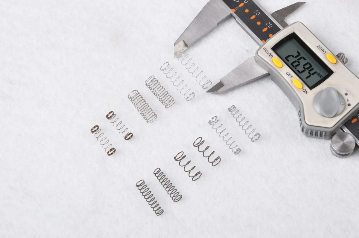
Before you measure:
- Take the spring out of the assembly. Note how it was installed first: photograph it in place, and write down the installed length or angle.
- Clean it. Wipe off oil and dirt. Heavy rust or scale changes the wire size; measure on a clean spot.
- Do not stretch, compress or wind it “to see how it feels”. Taking a spring past its working range can give it a permanent set, and then the sample no longer shows the original free length.
- Measure two or three springs if you have them, from the same position in the machine. A broken or sagged spring can mislead, so use the one in best condition and note which is which.
- Record values in millimeters or inches. Imperial readings are fine if you use them consistently and state the unit on every value. Wire gauge numbers are not a safe way to give wire size, because there are several gauge systems and the same number means different diameters in each [2].
Spring dimensions: the five measurements every spring needs
Every helical spring, whatever its type, starts with the same five numbers. The diagram shows them on a compression spring.
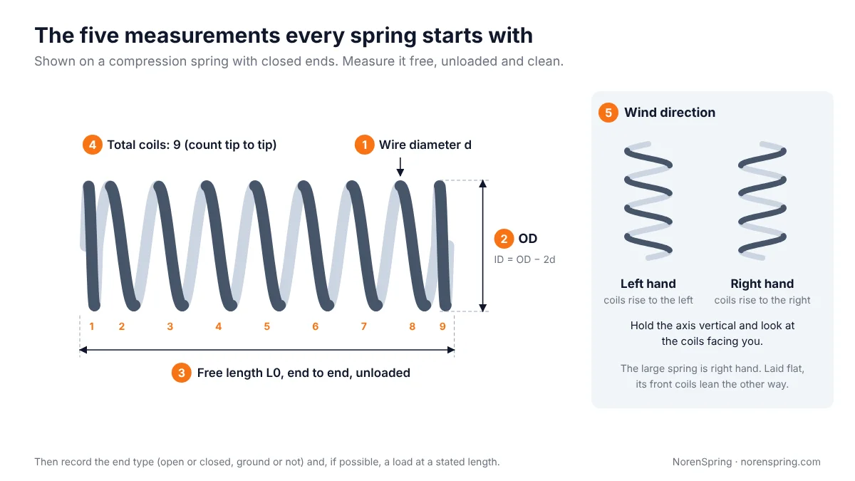
| # | Measurement | Symbol | How to measure | Record to |
|---|---|---|---|---|
| 1 | Wire diameter | d | Micrometer on the wire, several places | 0.01 mm (0.0005 in) |
| 2 | Outside diameter (and inside diameter) | OD, ID | Caliper across the coils, several places; ID with pins or inside jaws | 0.1 mm (0.005 in) |
| 3 | Free length | L0 | Spring standing free, end to end | 0.1 mm (0.005 in) |
| 4 | Total coils | Nt | Count turns from one wire tip to the other | quarter coil |
| 5 | Wind direction | LH / RH | Axis vertical, look at the coils facing you | — |
Two quick checks catch most errors. First, the mean diameter D = OD − d, and the spring index C = D / d should usually fall between about 4 and 12. Our spring index guide explains why. Second, OD − ID should equal 2d. If your figures do not agree with this, measure again.
How to measure wire diameter
Measure the wire diameter with a micrometer on a straight or gently curved part of the wire, at two or three places and at two positions turned 90° apart. On a compression spring, measure an active coil in the middle of the spring rather than a ground end coil. On an extension spring, measure the body, not the hook. On a torsion spring, a straight leg is the easiest place to measure. Take the average, and note it if the readings differ by more than a few hundredths of a millimeter, since the wire may be worn or out of round.
Wire diameter has the largest effect on how the spring behaves. The rate of a compression spring is k = G·d⁴ / (8·D³·Na), so a 5% increase in wire size makes the spring about 22% stiffer, and a 5% decrease makes it about 19% softer. A torsion spring follows the same fourth-power rule. An error of 0.05 mm on 1 mm wire is a 5% error, which is why a caliper reading is not enough for small springs. Our spring rate guide shows the full formula and the effect of each input.
Two things change the reading:
- Coatings. Powder coat, paint and thick plating add to the wire. A coating of thickness t adds 2t to the measured wire diameter. Measure on a spot where the coating has worn off, scrape a small area, or measure the coating with a thickness gauge and subtract it. Our spring finishes guide shows how much each finish adds.
- Wear and corrosion. Pitted or worn wire reads thin. Measure the cleanest section, and say on the sheet that the sample is worn.
If you can, note what the wire looks like: bright, black, zinc plated, painted, or stainless (often only weakly magnetic). The manufacturer still needs to confirm the material, but the appearance narrows it down. Our spring wire material guide compares the common grades.
How to measure a compression spring
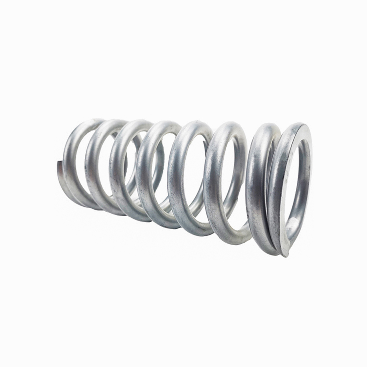
To measure a compression spring, take the five basic measurements and then add the end type, the active coil count and the solid height.
Outside diameter. Close the caliper jaws lightly across the coils at three or four places along the spring and turned around the axis. Record the largest value, because that is the one that has to fit in a bore. End coils can be slightly smaller or larger than the body, so measure the body as well as the ends if they differ.
Inside diameter. Measure it if the spring works over a rod or pin. Use pin gauges or the inside jaws of the caliper, and record the smallest value. Say which diameter is critical to the fit: OD for a bore, ID for a rod.
Free length. Stand the spring on a flat surface and measure its height without pressing on it. A height gauge or a caliper’s depth rod, lowered until it just touches, works better than closing the caliper jaws across the ends, which can squeeze a light spring. If the ends are not square, measure at the highest point.
End type. Look at the last coil at each end:
| End type | What you see | Total vs active coils |
|---|---|---|
| Open (plain) | Last coil has the same pitch as the rest; wire end not touching | Na = Nt |
| Open, ground | As above, end ground flat | Na = Nt − 1 |
| Closed, not ground | Last coil closed against the next one; wire end round | Na = Nt − 2 |
| Closed and ground | Last coil closed, end ground flat so the spring stands square | Na = Nt − 2 |
Active coil relations from Shigley, Table 10-1 [12], as used in our spring rate and spring index guides.
Solid height. This is the length when every coil touches. If you can, press the spring to solid on a tester and read the length. If you cannot, calculate it from the total coils: about Nt × d for ground ends and (Nt + 1) × d for unground ends. The real value runs slightly higher because of pitch variation and coating, so treat it as a minimum. The spring index guide has a table for all four end types.
Squareness. For a spring that must stand upright or load evenly, stand it beside a square and turn it slowly. The gap at the top between the spring and the square shows how far it leans. Note it if the spring visibly leans.
When you have these, the compression spring specification guide shows how to turn them into a drawing with a load at a stated length.
How to measure an extension spring
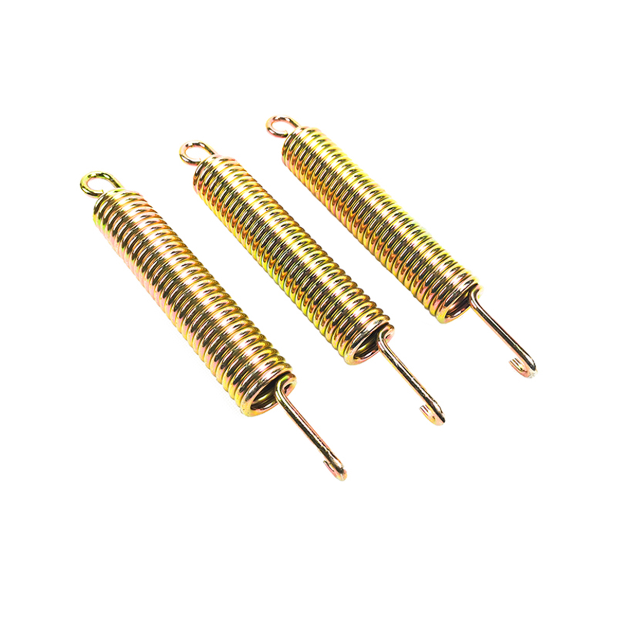
To measure an extension spring, measure the length inside the hooks, the body length and the hook form and position, as well as the wire, OD and coil count.
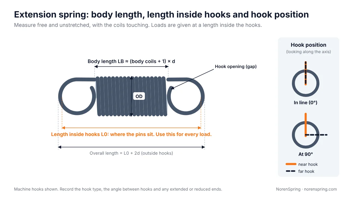
Length inside hooks. This is the free length of an extension spring: the distance between the inner surfaces of the two hooks, where the pins or anchor points sit. Use the inside jaws of a caliper, or measure the overall length outside the hooks and subtract two wire diameters. It is the length every load figure refers to, so it is the most important number on the sheet.
Body length. Measure the close-wound coil body only, from the outside of the first body coil to the outside of the last. On a close-wound body it is about (body coils + 1) × d, which is a useful check on your coil count.
Hooks. For each end, record:
- the hook type: machine hook, crossover hook, side hook, extended hook, reduced end or threaded insert (our extension spring specification guide shows each type);
- the hook opening, the gap between the end of the wire and the body;
- the length of any extended hook, measured to the inside of the loop;
- the position of the far hook relative to the near one, looking along the axis. In line (0°) and 90° are the most common, but other angles are possible.
Initial tension. A close-wound extension spring needs a certain pull before its coils separate. That pull is the initial tension, and it is set during coiling, so it cannot be seen. To estimate it, measure the force at two lengths that both open the coils, calculate the rate from them, and work back to the free length:
k = (F2 − F1) / (L2 − L1), then Fi ≈ F1 − k × (L1 − L0)
For example, a spring with 54.4 mm inside the hooks that pulls 43.6 N at 70 mm and 72.0 N at 85 mm has a rate of about 1.89 N/mm and an initial tension of about 14 N. This is the same relation, F = Fi + k × (L − L0), used in our extension spring guide [3][12]. Without a tester, hang known weights from a light spring and note the weight at which the coils just begin to open; it gives a rough figure.
Do not stretch a sample spring by hand to see how far it goes. Overstretching takes a permanent set and lengthens the spring, and then it no longer represents the original.
How to measure a torsion spring
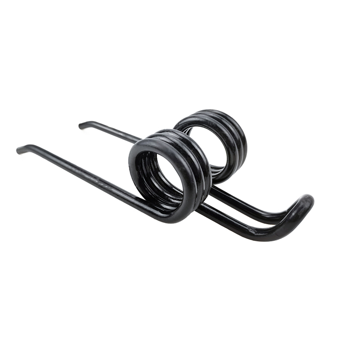
To measure a torsion spring, lay it flat and record the free angle between the legs, the length and shape of each leg, the body length and inside diameter, and the wind direction.
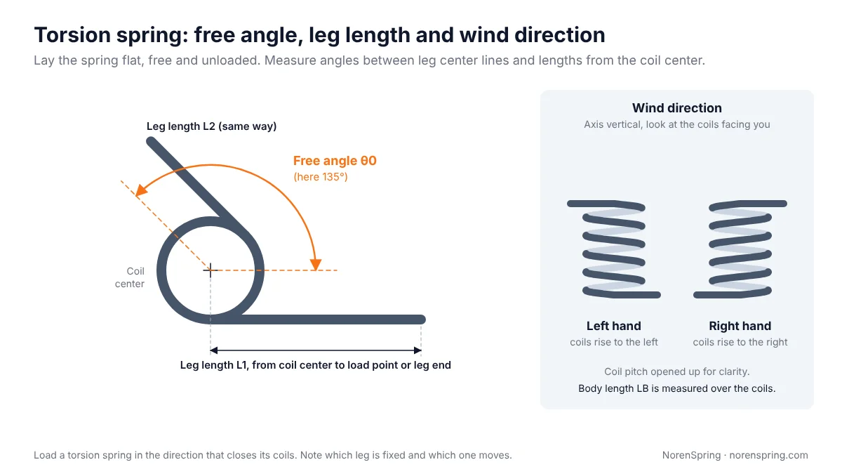
Free angle. Lay the spring on a sheet of paper with no load on the legs. Draw along the center line of each leg, extend the lines, and measure the angle between them with a protractor. Do not take this angle from a spring that is still installed: in place, the legs are already wound up to the installed angle. If the drawing will give angles as rotation from free, record the installed angle too.
Leg lengths. Measure each leg from the center of the coil (the axis) to the point where the load is applied or to the end of the leg. Say which you measured. For bent legs, trace the outline on the paper and dimension the bends, hooks and tips.
Body length and diameters. Measure the body length over the coils, the OD, and the ID. The ID matters because a torsion spring sits on an arbor and its ID closes as it winds up. Measure the arbor or pin it was mounted on as well.
Wind direction. Hold the spring with its axis vertical and look at the coils facing you. If they rise to the right, like a standard screw thread, the spring is right hand. If they rise to the left, it is left hand. A right-hand helix moves away from you when it is turned clockwise, as a normal screw does [4]. Getting the hand wrong is a costly mistake on a torsion spring. A torsion spring should be loaded in the direction that closes its coils [13]. A spring of the wrong hand has its legs mirrored; if it can be fitted at all, the load opens its coils, where stresses are higher, and it can fail early.
Which leg moves. Note which leg is fixed and which one moves, and which way it turns in the machine. A photo of the spring installed answers both questions.
The torsion spring specification guide explains how these values become torque at an angle and arbor clearance. For a spring with two coil bodies, see the double torsion spring guide; record the free angle, coil count and wind direction of each body separately. Spring tines are measured the same way, with a few extra dimensions for the mounting loop, as our spring tines guide shows.
How to count coils correctly
Count total coils by following the wire from one tip to the other, one full turn at a time. The easiest way is to lay a straight edge along one side of the spring and count how many times the wire crosses it. Then add the part turn at each end in quarters: look at where each wire tip sits around the circle compared with your starting line.
Count the total coils first and derive the active coils from the end type. For a compression spring with closed ends, active coils are the total minus two. For an extension spring, the body coils are the close-wound turns between the hooks. For a torsion spring, count the body coils; the part turn depends on where the legs leave the body, so the coil count and free angle are linked and should be measured together.
Errors of half a coil are common, especially at closed ends where the last turn is pressed against the next. They matter more than they look. On a spring with eight active coils, half a coil is a difference of about 6% in rate. Count twice, starting from opposite ends, and if the two counts disagree, count a third time.
Measuring load and rate
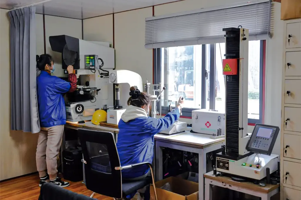
If you have access to a spring tester, measure force at two lengths (or torque at two angles) inside the spring’s working range. Two points define the rate and the force at any length in between, and they are what the manufacturer will check samples against.
- Compression springs. Compress to two lengths between about 20% and 80% of the available travel and record the force at each. The rate is k = (F2 − F1) / (L1 − L2).
- Extension springs. Stretch to two lengths inside the hooks, both above initial tension, and record the force at each.
- Torsion springs. On a torsion tester, record torque at two angles from free. Without one, mount the spring on a pin of the right size, hang a known weight on the leg at a measured distance from the coil center and measure the angle. Torque is weight times distance, M = F × R.
Our spring rate guide covers the two-point method in detail, with a calculator, and explains why a measured rate can differ from the formula.
If you have no tester, give the next best information: the installed length (or installed angle) and the length (or angle) at full travel. Measure these in the machine, between the seats, pins or stops the spring works against. A manufacturer can then estimate the load from the geometry and confirm it on sample springs.
Standards behind spring measurement
You do not need the standards to measure a replacement spring, but they explain the terms on a drawing and how a supplier will check your parts:
- ISO 22705-1:2021 and ISO 22705-2:2023 set out the measurement and test methods for cold-formed helical compression and extension springs made from round wire, such as free length, body length and hook length, excluding dynamic testing [5][6].
- ISO 2162-1 gives the simplified way compression, extension and torsion springs are drawn [7], and ISO 26909 defines spring terms [8].
- The European quality specifications are EN 15800 for cold-coiled compression springs (it replaced DIN 2095) [9], DIN 2097 for extension springs [10] and DIN 2194 for torsion springs [11].
Common measuring mistakes
| Mistake | What goes wrong | How to avoid it |
|---|---|---|
| Measuring a sagged, stretched or broken spring | Free length or free angle is wrong; the copy is weak or too long | Use the least worn sample; note its condition; give the installed length too |
| Squeezing the spring with the caliper jaws | Free length reads short on light springs | Use a height gauge or depth rod, or measure on a vision system |
| Confusing OD, ID and mean diameter | Spring does not fit the bore or rod | Label each figure; check that OD − ID = 2d |
| Wire measured with a caliper on a small spring | Rate off by 10% or more | Use a micrometer and average several readings |
| Ignoring the coating | Wire and OD read large, ID small | Measure bare wire or subtract 2 × coating thickness |
| Reading the wind direction with the spring lying flat | Hand reversed | Turn the axis vertical before deciding |
| Free angle taken from an installed torsion spring | Legs do not line up on the replacement | Measure with the spring removed and unloaded |
| Extension spring length measured over the body or outside the hooks | Loads quoted at the wrong length | Measure inside the hooks, where the pins sit |
| Coil count out by half a turn | Rate wrong by several percent | Count tip to tip twice, from both ends |
| Gauge number instead of a diameter | Wrong wire size | Give the wire size in mm or inches |
Spring measurement sheet for your RFQ
Copy this sheet into your inquiry and fill in what you measured. Rows 1 to 7 apply to every spring. Add the rows for your spring type. Leave a cell blank rather than guessing; the manufacturer can derive what is missing from the rest. The compression spring examples describe the same 2 mm wire, 20 mm OD spring used in our spring index guide.
| # | Measurement | Applies to | Example (replace with your value) |
|---|---|---|---|
| 1 | Spring type and where it is used | All | e.g. compression, return spring on a feed gate |
| 2 | Wire diameter d (and how measured) | All | e.g. 2.00 mm, micrometer, bare spot |
| 3 | Outside diameter OD / inside diameter ID, and which is critical | All | e.g. OD 20.0 mm max, works in a 21 mm bore |
| 4 | Total coils Nt | All | e.g. 10 |
| 5 | Wind direction | All (essential for torsion) | LH / RH |
| 6 | Material or appearance, finish and color | All | e.g. black coated carbon steel |
| 7 | Sample condition | All | e.g. new spare / used, sagged / broken |
| 8 | Free length L0 | Compression | e.g. 50.0 mm |
| 9 | End type | Compression | e.g. closed and ground |
| 10 | Solid height (measured or calculated) | Compression | e.g. 20.0 mm, calculated as Nt × d |
| 11 | Length inside hooks | Extension | e.g. 54.4 mm |
| 12 | Body length, hook type, hook opening, hook position | Extension | e.g. 33.6 mm, machine hooks, far hook at 90° |
| 13 | Free angle between legs | Torsion | e.g. 135° |
| 14 | Leg lengths from coil center, leg shapes, which leg moves | Torsion | e.g. L1 40 mm straight, L2 32 mm with hook; L2 moves |
| 15 | Arbor or pin diameter | Torsion | e.g. 12 mm pin |
| 16 | Load at length, or torque at angle (one or two points) | All, if measured | e.g. 34 N at 40 mm, 68 N at 30 mm |
| 17 | Installed and fully loaded length or angle | All | e.g. 40 mm installed, 30 mm at full stroke |
| 18 | Environment, duty and quantity | All | e.g. outdoor, about 10,000 cycles per season, 500 pcs |
Add photos: the spring on the bench beside a ruler, and the spring installed. For an extension or torsion spring, a photo looking along the axis shows the hook or leg position better than a description.
Sending a sample instead
If measuring is difficult, send the spring itself. Most projects start from a drawing or sketch, but we also work from physical samples. When you send one:
- send two or three pieces if you have them, and mark any that are worn, sagged or broken;
- include a photo of the spring installed and the installed length or angle;
- tell us what is wrong with the current part, for example losing force, breaking at the hook, or rubbing in the bore.
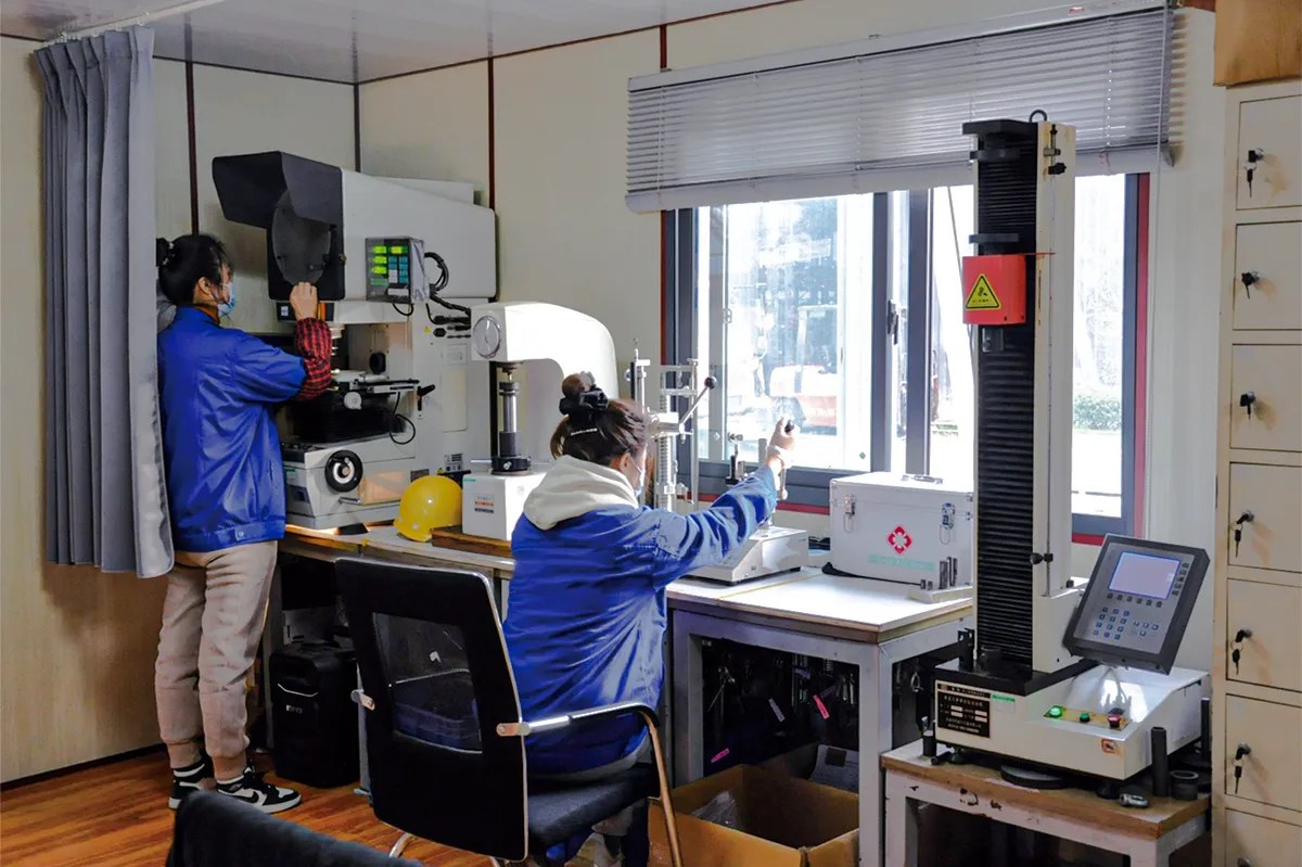
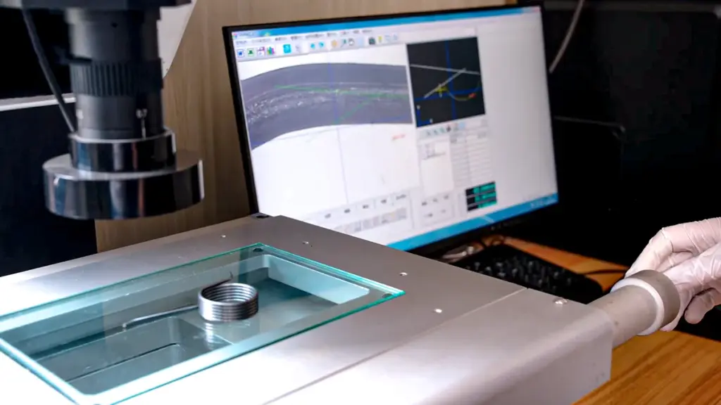
Our engineers can measure the sample on a Keyence IM-8000 series vision measuring system and a Mitutoyo LH-600 series height gauge, check load and rate on JISC PRO series spring testers and torque on JISC PRO-T series torsion testers, and confirm the material with a Thermo Scientific Niton XL2 analyzer. We can then propose a drawing for your approval before samples are made.
We send engineering feedback or a quotation within 24 hours, and there is no fixed minimum order quantity: small-batch prototypes and high-volume production are both supported. See our compression, extension and torsion spring ranges.
Have a spring to match?
Send your measurement sheet, photos or the sample details through our contact page. An engineer will check the figures, ask for anything missing, and quote from there.
Send your measurements See our capabilities
Frequently asked questions
How do you measure a spring?
Measure the wire diameter with a micrometer, the outside diameter and free length with a caliper, count the total coils from tip to tip, and note the wind direction. Those five spring dimensions describe the size of any helical spring. Add the end type for a compression spring, the length inside the hooks for an extension spring, or the free angle and leg lengths for a torsion spring.
How do I measure spring length?
Measure the spring free, with no load. For a compression spring, stand it on a flat surface and measure its height without pressing on it. For an extension spring, measure the length inside the hooks, between the surfaces where the pins sit. For a torsion spring, the length that matters is the body length over the coils, plus the length of each leg from the coil center.
How do I tell if a spring is left or right hand?
Hold the spring with its axis vertical and look at the coils facing you. If they rise to the right, like a standard screw thread, it is right hand. If they rise to the left, it is left hand. Do not judge it with the spring lying flat: turned on its side, the slope of the coils rotates 90°, so the rise-to-the-right rule only works with the axis vertical.
How do you measure spring tension?
Measure the force at a stated length on a spring tester, ideally at two lengths so the rate can be calculated. For an extension spring, both readings should be above the initial tension; the initial tension itself is estimated by working back from the two readings to the free length. For a torsion spring, measure torque at two angles. Without a tester, hanging known weights gives a rough figure. The spring rate guide explains the method.
Can a manufacturer copy a spring from a sample?
Yes. A spring manufacturer can measure the geometry, test the force and check the material from a sample, then propose a drawing for approval. The result is better if you send more than one sample, say which are worn, and give the installed length or angle and what the current spring is doing wrong. NorenSpring works from physical samples as well as drawings.
About the authors
This guide was prepared by the NorenSpring engineering team, which designs and manufactures custom compression, extension and torsion springs and wire forms in Xuzhou, China. Technical review by Feng Yulin, General Manager and senior structural engineer, who has 15 years of spring R&D experience and more than 30 national patents. NorenSpring holds IATF 16949, ISO 9001, ISO 13485, ISO 14001 and ISO 45001 certifications. More about NorenSpring. Methods and figures were last checked on October 14, 2026.
Sources
The numbers in square brackets in the text refer to this list.
- Keyence, Measurement System Basics: Abbe’s principle. Source for the statement that outside micrometers follow Abbe’s principle and hand calipers do not. Retrieved 2026-10-14.
- ASTM International, ASTM B258, Standard Specification for Standard Nominal Diameters and Cross-Sectional Areas of AWG Sizes of Solid Round Wires Used as Electrical Conductors. Primary source for one gauge system (AWG) and its tabulated diameters. Secondary: Wikipedia, Wire gauge, for the other systems in use (Birmingham, SWG and others). Retrieved 2026-10-14.
- Engineers Edge, Extension Spring Force Formula. Source for total force = initial tension + rate × deflection, used to estimate initial tension from two readings; the same relation is given in Shigley [12]. Retrieved 2026-10-14.
- ISO, ISO 5408:2009, Screw threads — Vocabulary, which defines right-hand and left-hand threads. Secondary: Wikipedia, Screw thread: handedness, for the plain-language description that a right-hand thread moves away from the viewer when turned clockwise. Retrieved 2026-10-14.
- BSI, BS EN ISO 22705-1, Springs. Measurement and test parameters. Part 1: Cold formed cylindrical helical compression springs (identical to ISO 22705-1:2021). Retrieved 2026-10-14.
- ISO, ISO 22705-2:2023, Springs — Measurement and test parameters — Part 2: Cold formed cylindrical helical extension springs. Source for the scope (general characteristics, excluding dynamic testing) and the parameters free length, body length and hook length. Retrieved 2026-10-14.
- BSI, BS EN ISO 2162-1, Technical product documentation. Springs. Simplified representation. Retrieved 2026-10-14.
- AFNOR, NF EN ISO 26909, Springs — Vocabulary. Retrieved 2026-10-14.
- BSI, BS EN 15800:2008, Cylindrical helical springs made of round wire. Quality specifications for cold coiled compression springs (UK adoption of CEN EN 15800:2008). Retrieved 2026-10-14.
- DIN Media, DIN 2097, Helical springs made of round wire; quality specifications for cold coiled tension springs. Retrieved 2026-10-14.
- DIN Media, DIN 2194, Helical springs made of round wire and rod — Cold coiled torsional springs (leg springs) — Quality specifications. Retrieved 2026-10-14.
- R. G. Budynas and J. K. Nisbett, Shigley’s Mechanical Engineering Design, 11th edition, McGraw-Hill, 2020, chapter 10 (Mechanical Springs). Source for the compression spring rate formula, the end-type relations for active coils and solid height, the extension spring force relation F = Fi + k(L − L0), and the usual spring index range.
- Newcomb Spring, guidance on identifying the direction of wind of a torsion spring, and Lee Spring, Learn About Torsion Springs (manufacturer guidance, web pages). Background for the wind direction check and the rule that torsion springs are loaded in the direction that closes the coils; also cited in our torsion spring specification guide.