

In this article
- Key takeaways for specifying an extension spring
- What defines an extension spring?
- 1. Start with the lengths: free, installed and maximum
- 2. Initial tension: the load before the spring starts to stretch
- 3. Choose the end type: hooks, loops and plugs
- 4. Material and finish
- 5. Safety in heavy-duty positions
- 6. Tolerances and inspection
- Example: a deck belt spring that lost tension
- Custom extension spring RFQ checklist
- What happens after you send the inquiry
- Have a drawing or a sample spring?
- Frequently asked questions
- About the authors
- Sources
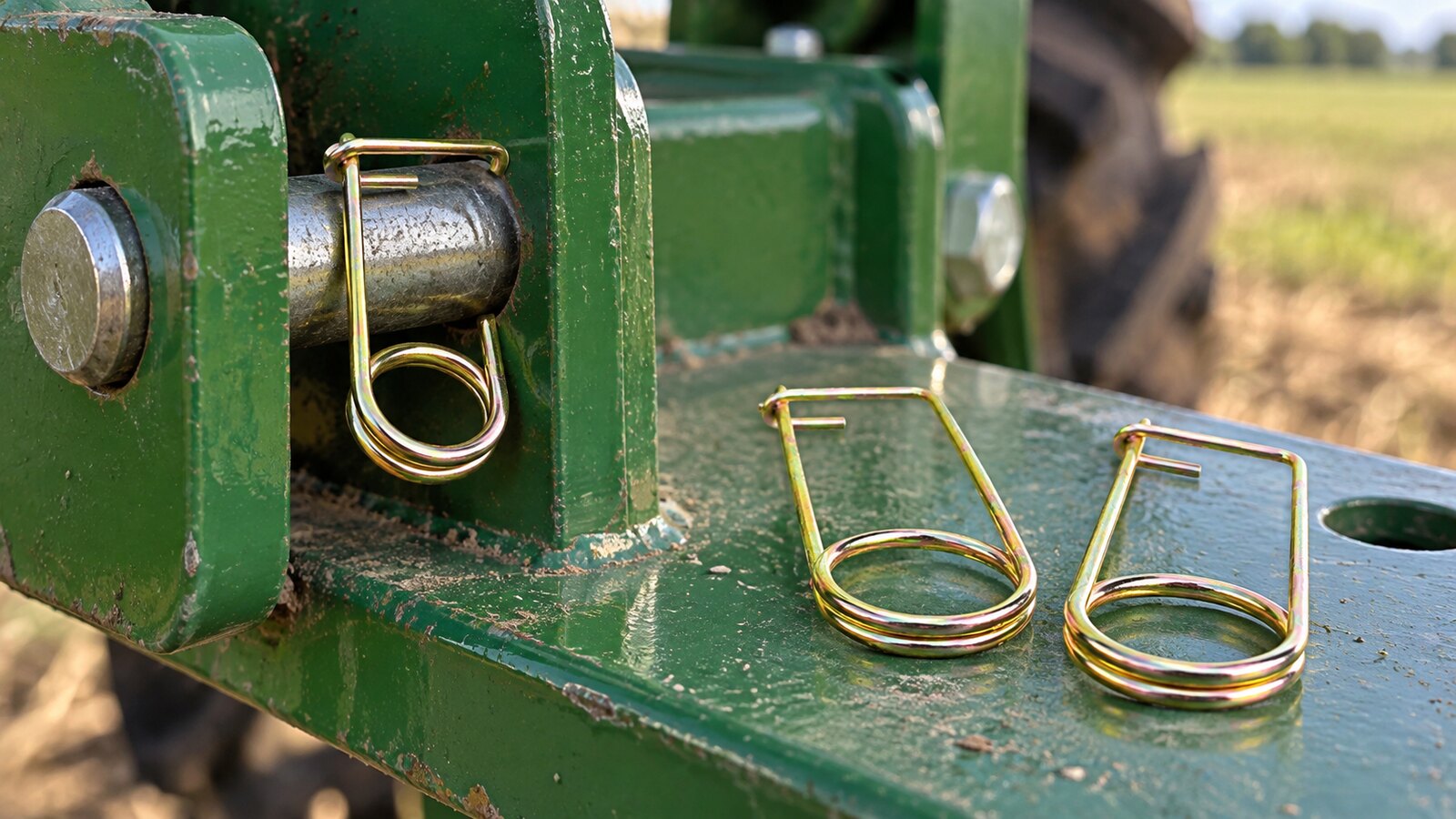
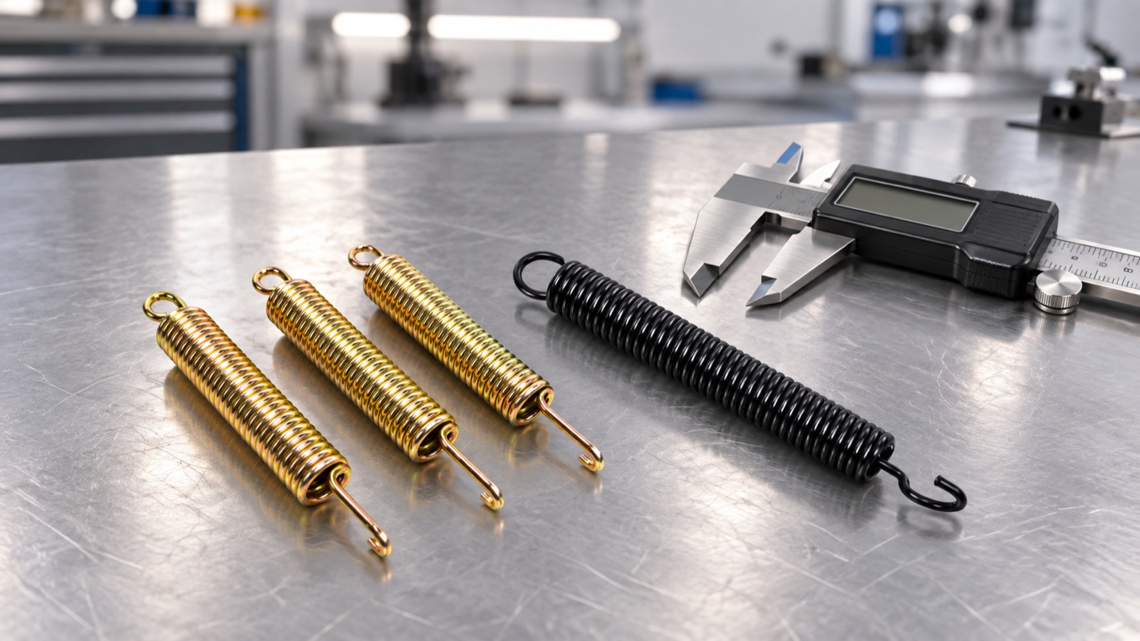
Cover image: an AI-generated illustration based on photos of our extension springs, not a photograph.
To get an accurate quote for a custom extension spring, send the manufacturer six things: the free length inside the hooks, the load you need at two stated lengths, the longest length the spring will ever reach, the hook type and how the two hooks line up, the wire or outside diameter limits, and the material or operating environment. Add the quantity and any initial tension requirement, and an engineer can work out the rest.
Extension springs fail in their own way. The coil body is rarely the weak point. Most problems come from the hooks, from initial tension that was never specified, or from a spring stretched further in assembly than anyone planned. This guide goes through each input in the order we check it and ends with a checklist you can paste into your RFQ. It is the third in a series with our compression spring specification guide and torsion spring specification guide. Bent-wire parts are covered in our wire forms design guide.
Key takeaways for specifying an extension spring
- Give loads at lengths. “43 N at 70 mm and 72 N at 85 mm inside hooks” defines the spring. A rate on its own does not, because initial tension moves the whole load line.
- Initial tension is real load, but it has limits. It is set during coiling and falls within a range that depends on the spring index. Ask for a value only if the part must not move below a certain pull.
- The hook usually fails first. Stress at the hook bend can exceed the body stress. In our worked example, a tight bend raises it by about 48%.
- State the maximum length. Overstretching in assembly or service permanently lengthens the spring. Tell the manufacturer the longest length the part will see.
- Plan for breakage where it matters. A broken extension spring releases stored energy. Heavy-duty positions may need a containment cable or a drawbar design.
What defines an extension spring?
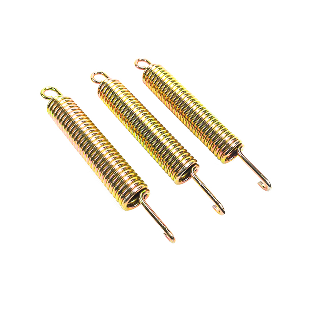
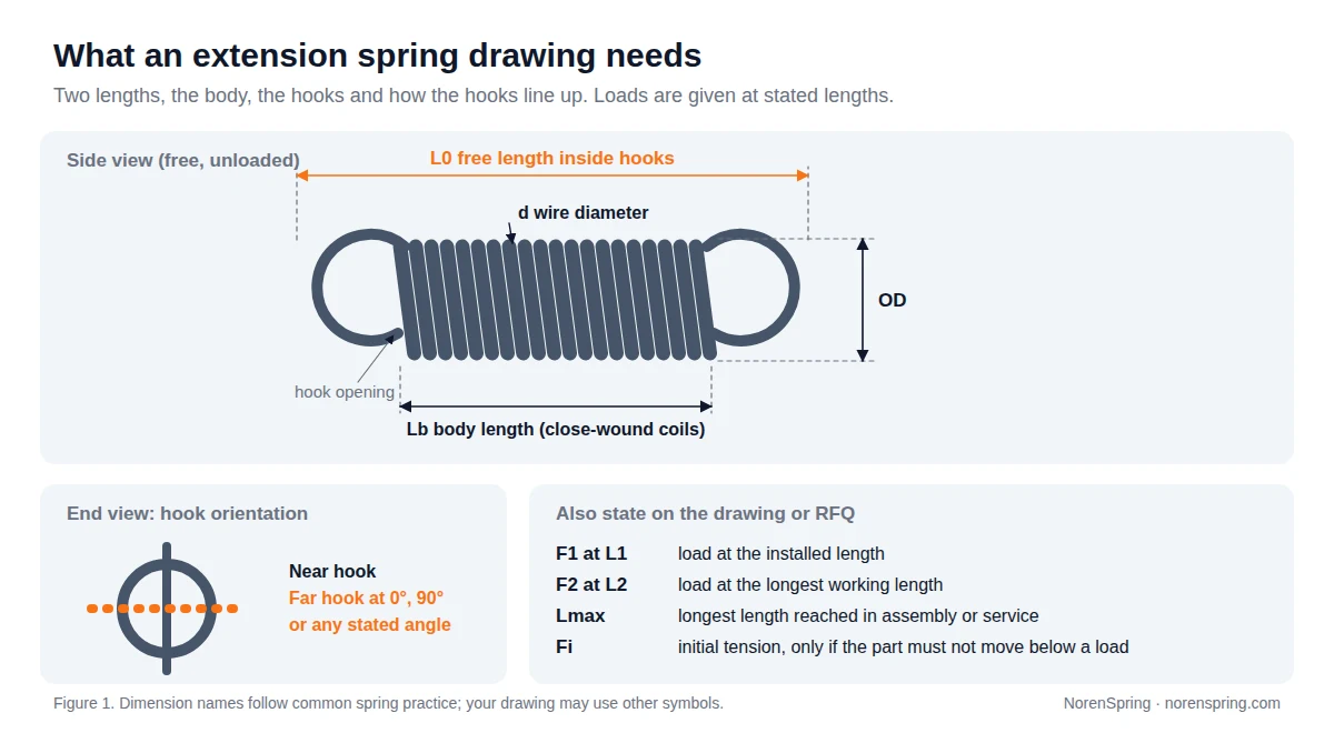
An extension spring is a helical spring that resists pulling. It is usually close-wound, so the coils touch when the spring is free, and it carries its load through hooks or loops at each end. Unlike a compression spring, it has no solid height to stop it. The drawing therefore has to fix the lengths and loads that keep it in its safe range.
| Symbol | Name | Why it matters |
|---|---|---|
| d | Wire diameter | Largest single effect on rate and stress. |
| OD / D | Outside / mean diameter | OD must clear the housing. Mean diameter D = OD − d, and the index C = D / d. |
| Nb | Body coils | Sets the rate together with d and D. Usually derived by the manufacturer. |
| L0 | Free length inside hooks | Distance between the inner surfaces of the two hooks with no load. Every working length is measured the same way. |
| Lb | Body length | Close-wound body only, about (Nb + 1) × d. |
| F1 / L1, F2 / L2 | Working points | The load you need at the installed and fully extended lengths. |
| Lmax | Maximum length | The longest the spring is ever stretched, including during assembly. |
| Fi | Initial tension | The pull needed before the coils start to separate. |
Our extension spring product page shows the forms we make. The inputs above apply to all of them.
1. Start with the lengths: free, installed and maximum
Before any load figure, describe where the spring is anchored. Give the distance between the two pins, holes or brackets when the mechanism is at rest and when it is at full travel. Those two distances become L1 and L2. Say whether the spring is stretched further during assembly, for example when it is hooked over a pin by hand or with a tool.
The longest of these, Lmax, is the number most often missing from an RFQ. Stretching a spring past its design limit gives it a permanent set, so it no longer returns to its original free length. A replacement spring that “went soft” after installation was often simply overstretched while it was being fitted.
Also give the space around the spring. A spring that rubs against a housing or neighbouring part wears through its coils and loses load. When the spring works close to other parts, state the largest outside diameter that fits.
2. Initial tension: the load before the spring starts to stretch
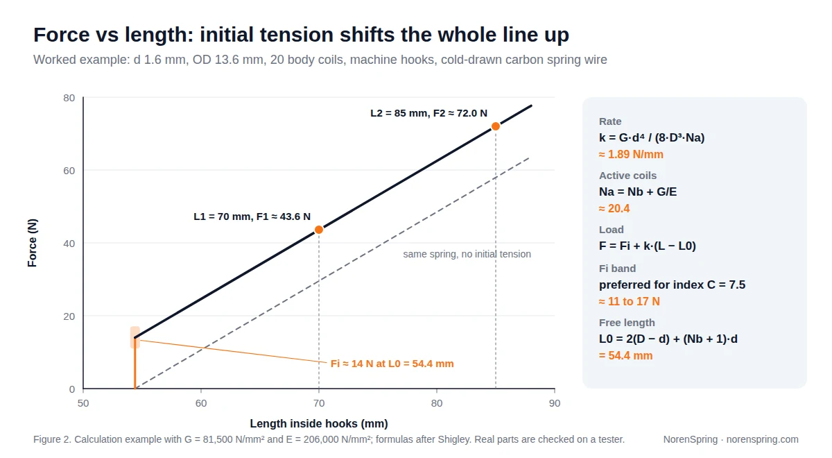
Initial tension is the force that holds the coils of a close-wound extension spring together. The coiling machine produces it by twisting the wire against the previous coil as the body is formed (Gutekunst Federn, Information on extension springs, retrieved 2026-09-30). Until the pull exceeds it, the spring does not stretch at all. Above it, force rises in a straight line:
F = Fi + k × (L − L0), where k is the spring rate and L is the length inside the hooks (Engineers Edge, Extension Spring Force Formula, retrieved 2026-09-30).
That is why a rate alone does not describe an extension spring. Two springs with the same rate but different initial tension give different loads at every length. To measure the rate itself, take two readings above initial tension, as shown in our spring rate guide.
How much initial tension is possible?
Initial tension cannot be chosen freely. It depends mainly on the spring index C = D / d. Shigley’s Mechanical Engineering Design gives the preferred range of initial-tension stress as τi = 231 / e^(0.105C) ± 6.9 × (4 − (C − 3) / 6.5) MPa, with Fi = τi × π d³ / (8D). Springs coiled inside this band can be made repeatably. Values far outside it are difficult or impossible to hold in production.
Heat treatment matters as well. Stress relieving after coiling reduces initial tension, and higher tempering temperatures and longer times remove more of it (Gutekunst Federn). This is one reason the manufacturer confirms initial tension on sample springs rather than on paper.
A worked example
Take a spring in cold-drawn carbon spring wire with d = 1.6 mm, OD = 13.6 mm (so D = 12.0 mm and C = 7.5), 20 body coils and a machine hook at each end. We use G = 81,500 N/mm² and E = 206,000 N/mm², typical values for this wire.
- Active coils. Hooks add a little deflection of their own, an effect studied in detail by Paredes, Stephan and Orcière (2019). Shigley accounts for it by counting Na = Nb + G/E ≈ 20.4.
- Rate. k = G d⁴ / (8 D³ Na) ≈ 1.89 N/mm.
- Initial tension. For C = 7.5 the preferred τi is about 82 to 128 MPa, which gives Fi ≈ 11 to 17 N. We design for 14 N.
- Free length. With machine hooks, L0 = 2(D − d) + (Nb + 1) d = 54.4 mm.
- Loads. At L1 = 70 mm, F1 ≈ 14 + 1.89 × 15.6 ≈ 43.6 N. At L2 = 85 mm, F2 ≈ 72.0 N.
This is a calculation to show how the inputs connect, not a rated part. For your own spring, send the lengths and loads, and we calculate and then test.
When should you specify initial tension?
Specify it when the part must stay closed or silent below a certain pull. Examples are a latch that must not rattle, a pedal that must hold its rest position, or a belt tensioner that must keep a minimum load. If the spring only has to deliver two working loads, give those and let the manufacturer choose initial tension within the practical band. Over-constraining it narrows the design options and can raise cost.
3. Choose the end type: hooks, loops and plugs
The ends set the free length, the line along which the load acts and, very often, the spring’s life. Engineers Edge, drawing on Wahl’s Mechanical Springs, calls the base of the hook “the weakest point in an extension spring” (Extension Spring Hook Design, retrieved 2026-09-30).
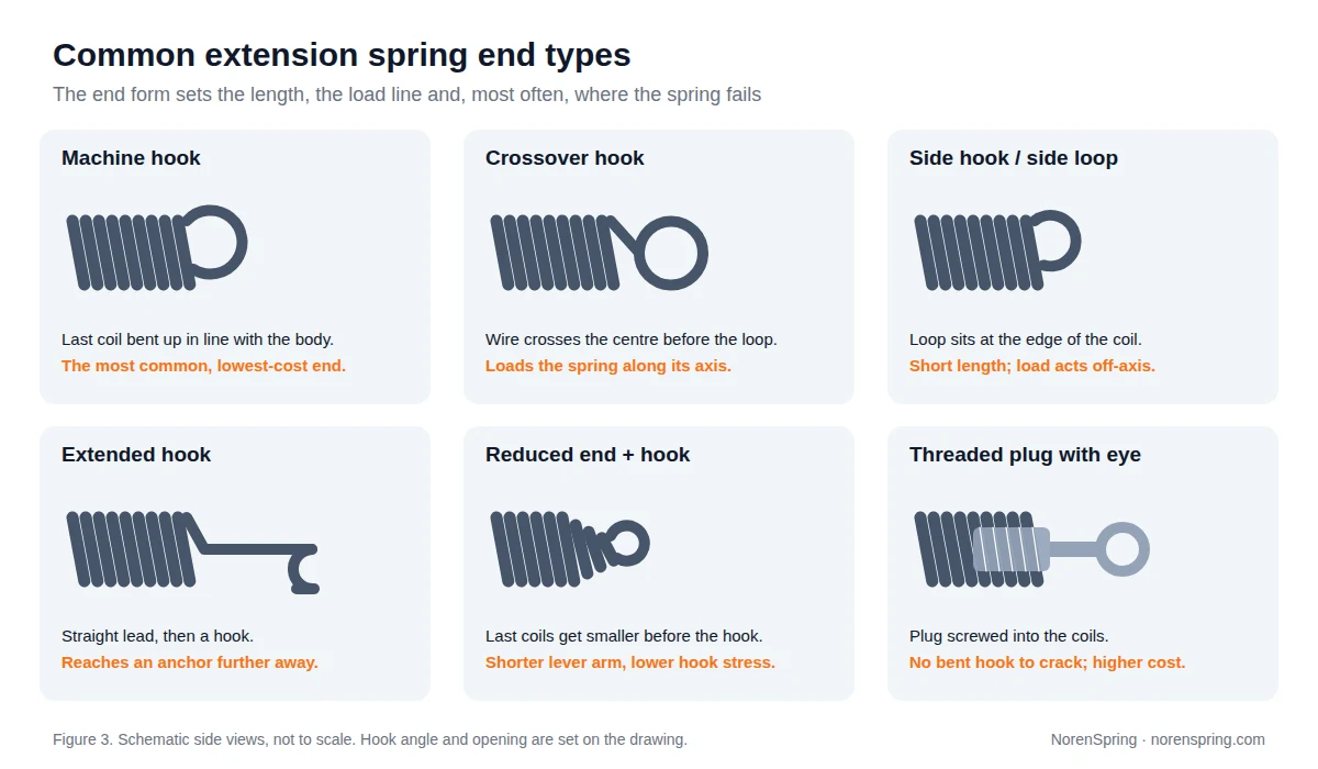
- Machine hook. The last coil is bent up in line with the body. It is the most common and lowest-cost end.
- Crossover (cross-centre) hook. The wire crosses the centre of the coil before forming the loop, so the load acts along the spring axis.
- Side hook or side loop. The loop sits at the edge of the coil. It keeps the spring short, but the load acts off-axis.
- Extended hook. A straight lead before the hook reaches an anchor point further away. It adds length, so give the length inside hooks, not only the body length.
- Reduced end with hook. The last coils get smaller before the hook. This shortens the lever arm at the hook and lowers its stress.
- Threaded plug or insert. A plug screwed into the end coils carries the load, so there is no bent hook to crack. It costs more but suits high-cycle or high-load positions.
State how the two hooks line up. A far hook at 0° or 90° to the near hook is common, and other angles are possible. If your mechanism twists the spring to make the hooks meet their pins, the hooks see extra bending.
Why the hook bend radius matters
Where the hook turns away from the body, the wire is bent tightly and carries both torsion and bending. Wahl’s formulas, as given by Engineers Edge, raise the torsional stress at that bend by a factor K = (4C2 − 1)/(4C2 − 4), where C2 = 2r2/d and r2 is the mean radius of the bend, equal to the inside bend radius plus d/2 (Extension Spring Coil Loop Stress, retrieved 2026-09-30). The tighter the bend, the higher the stress.
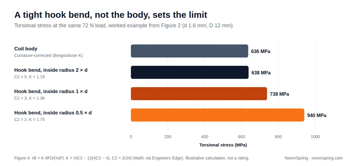
In our worked example at 72 N, the body stress is about 636 MPa. With an inside bend radius of half the wire diameter, the stress at the hook bend reaches about 940 MPa, roughly 48% higher. With an inside radius of twice the wire diameter, it drops to about 638 MPa, level with the body. Engineers Edge recommends an inside radius of at least twice the wire diameter. If your drawing does not allow that, say so. We can then look at a reduced end, a different hook type or a larger wire.
4. Material and finish
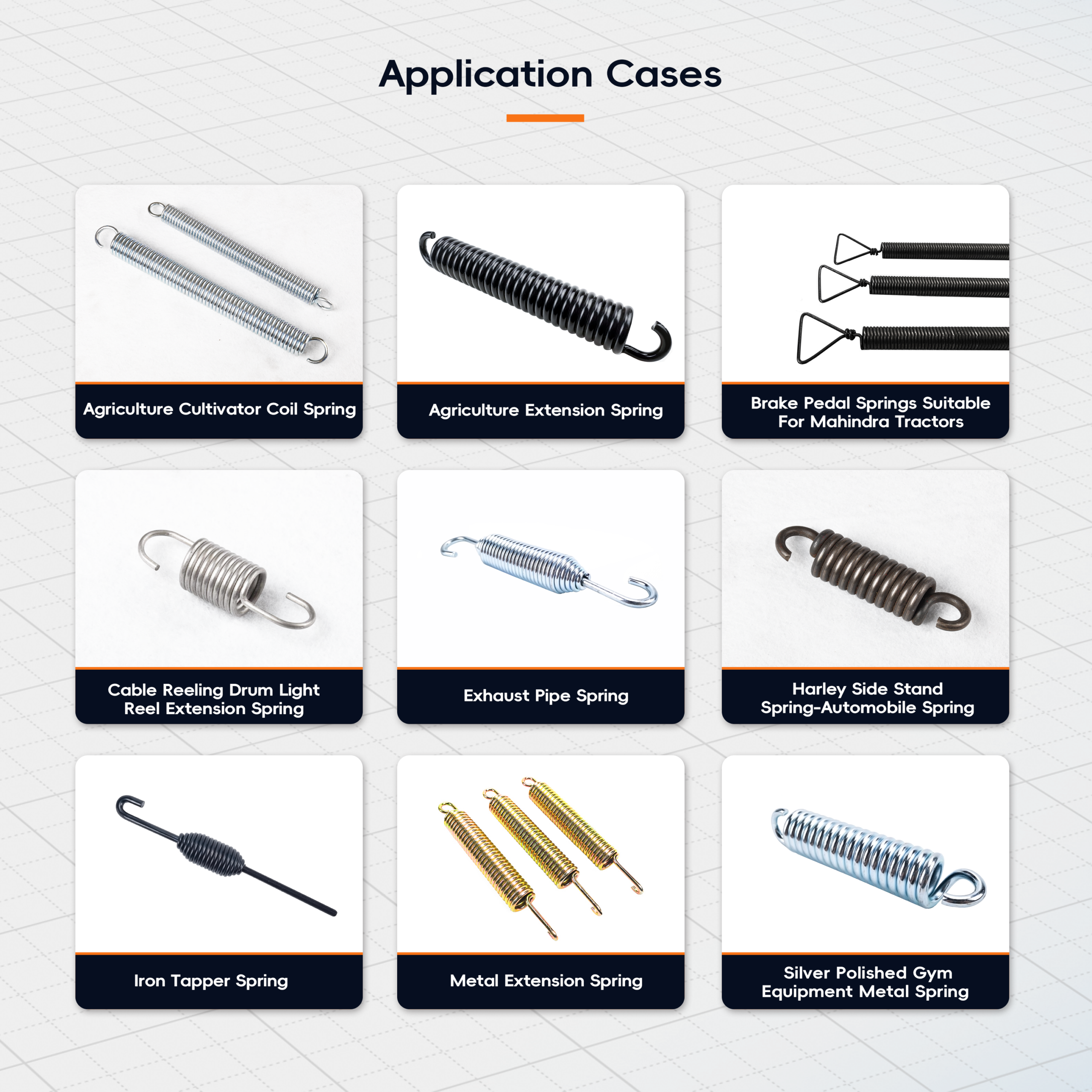
Choose the material for the load, the environment and the finish you need. Our spring wire material guide compares the grades in detail. For the nine extension springs in our case portfolio, our production team lists these materials and finishes:
| Part | Material | Usual finish |
|---|---|---|
| Agriculture extension spring | 65Mn / SWC | Zinc plating |
| Brake pedal spring for tractors | SWC / 65Mn | Zinc plating |
| Cable reel extension spring | SWP-B | Zinc plating |
| Exhaust pipe spring | Stainless steel 304 | Passivation |
| Motorcycle side stand spring | SWC | Zinc plating |
| Metal extension spring | SWC / SWP | Zinc or nickel plating |
| Iron tapper spring | Carbon steel | Black oxide |
| Gym equipment spring | Stainless steel 304 | Polishing |
| Agriculture cultivator coil spring | 50CrVA | Black oxide |
Two points apply to most extension springs. First, stainless steel resists corrosion near heat and moisture, as on the exhaust spring, but it has a lower modulus than carbon steel, so the same geometry gives a lower rate. Second, electroplated high-strength springs are at risk of hydrogen embrittlement. Baking after plating reduces that risk, and ASTM B850 is the usual reference (ASTM International, retrieved 2026-09-30). Tell us if a finish is required by your drawing or a customer specification. Our spring finishes guide explains how to choose and specify one. For fitness equipment, where the pull has to feel the same on every machine, see our sports and recreation spring solutions.
5. Safety in heavy-duty positions
An extension spring stores energy, and if it breaks, the pieces can fly. The US garage door industry association DASMA advises that doors with extension springs need “a safety cable that runs through the spring”, because “if the spring breaks, it may cause injury” (DASMA, Garage Doors safety tips, retrieved 2026-09-30).
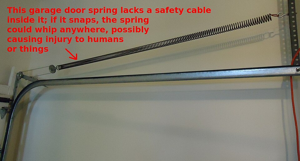
The same thinking applies to machinery. Where a heavy spring works near people, consider a containment cable or guard. Another option is a drawbar spring, in which a compression spring is loaded through two drawbars. Lee Spring notes that drawbar springs “offer a built-in definite stop” and keep carrying a static load at their maximum extended length. If the application is safety-critical, tell us at the inquiry stage, so the design and the testing plan reflect it.
6. Tolerances and inspection
Agree tolerances on what your assembly actually needs: usually the length inside hooks, one or two loads at stated lengths, and the hook opening and angle. Tolerances on every dimension at once are rarely achievable at a sensible cost, because the loads, lengths and diameters depend on each other. DIN 2097 sets out quality requirements for cold-coiled extension springs and is a common reference (DIN 2097 catalogue entry, retrieved 2026-09-30). The calculation method is in EN 13906-2 (BSI, retrieved 2026-09-30).
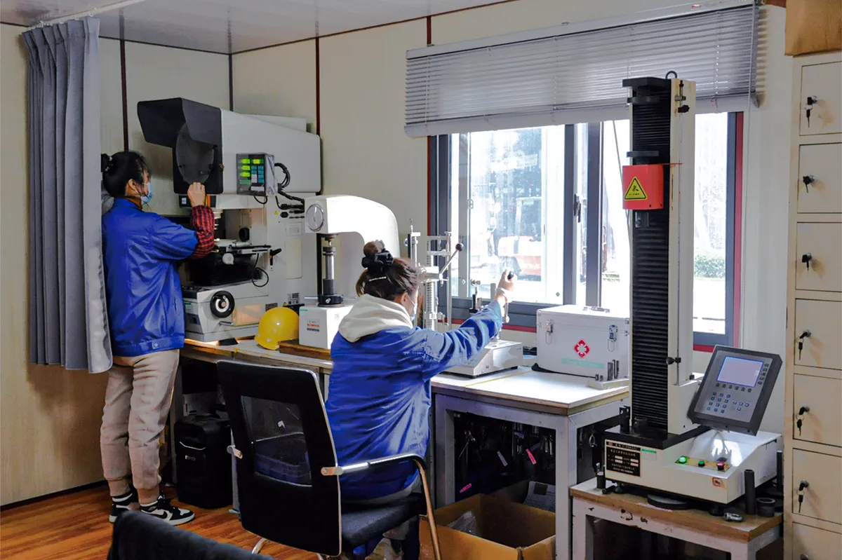
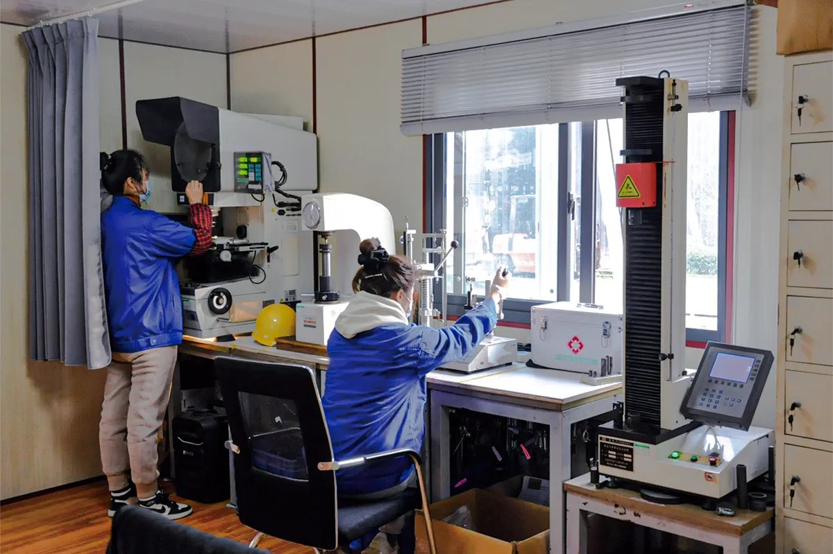
At NorenSpring, loads, rate and initial tension are measured on spring testers, including an ALGOL PRO-01 series automatic spring tester for batch checks and JISC PRO and Aikoh 1311NR series tension and compression testers. Hook geometry and lengths are measured on a Keyence IM-8000 series vision measuring system. Material composition can be checked with a Thermo Scientific Niton XL2 analyzer. Inspection reports, material certificates and dimensional records are agreed at project setup.
Example: a deck belt spring that lost tension
A buyer in the USA needed a replacement deck belt extension spring compatible with John Deere mowing equipment. The spring they had been using lost tension under high-frequency operation, so the deck belt was no longer held tight enough.
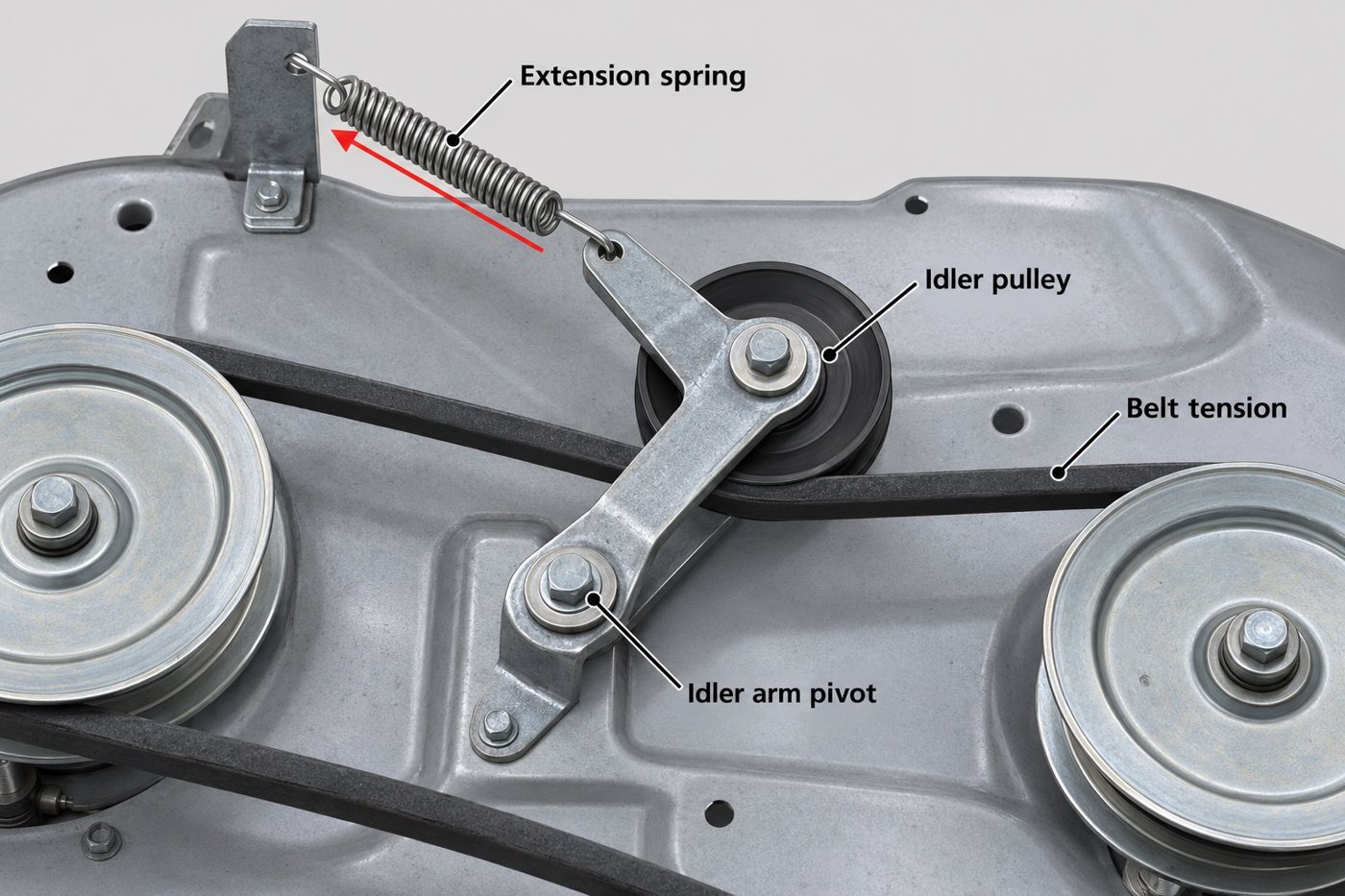
Working from the original part’s dimensions, our engineers redesigned the hook form, optimized the initial tension and improved fatigue performance, using high-strength spring steel. The spring passed installation testing on the equipment, and we now supply it as a replacement on a steady basis. Customer details are kept confidential. The inputs in this guide are the ones that mattered here: load at the installed length, initial tension, the hook form and the fatigue duty. See more parts on our extension spring case studies page and our agricultural machinery springs page.
Brand names are used only to identify compatible equipment; NorenSpring is not affiliated with these manufacturers.
Custom extension spring RFQ checklist
Copy this table into your inquiry and fill in what you know. Rows 1 to 5 are the minimum for an accurate quote. If you do not know row 6, we can derive it from the loads and space you give us.
| # | Item | Example |
|---|---|---|
| 1 | Free length inside hooks | 54.4 mm (or “derive”) |
| 2 | Loads at two lengths inside hooks | 43 N at 70 mm, 72 N at 85 mm |
| 3 | Maximum length in assembly or service | 90 mm |
| 4 | End type, hook opening and hook angle | Machine hooks both ends, far hook at 90° |
| 5 | Space limits | OD 14 mm max; clearance to housing 3 mm |
| 6 | Wire diameter, OD, body coils | d 1.6 mm, OD 13.6 mm, coils: derive |
| 7 | Initial tension (only if critical) | Must not open below 12 N |
| 8 | Material or environment | Carbon spring wire, outdoor, wet |
| 9 | Surface finish | Zinc plated and baked / black oxide / none |
| 10 | Duty and safety | Belt tensioner, continuous vibration; near operator |
| 11 | Quantity, timing and records | 200 samples, then 20k/year; material cert + load report |
No drawing? A sample, a photo of it installed, and the two lengths it works between are enough to start.
What happens after you send the inquiry
Our 28+ engineers review each inquiry and send engineering feedback or a quotation within 24 hours. The requirement review checks loads, lengths, mounting points, environment and your drawing or sample. Tooling for the hook or loop form is then prepared, and samples are made for dimensional, load and fit approval. Samples usually take 7 to 15 working days, and production 15 to 30 working days. The exact lead time is confirmed at quotation, because it depends on material, tooling, quantity and approvals. CNC coiling sets body diameter and initial tension, the ends are formed, and the parts are stress relieved and finished. Inspection follows the agreed control plan before packing with export documentation. There is no fixed minimum order quantity. Our capabilities page explains each stage.
Have a drawing or a sample spring?
Send the drawing, CAD file (DWG, DXF, STEP or PDF) or photos you already have, with the loads and lengths you know. An engineer will confirm the missing values, check hook stress and initial tension, and quote from there.
Upload a drawing View extension springs
Frequently asked questions
What is the minimum information needed to quote an extension spring?
The free length inside the hooks, loads at two stated lengths, the maximum length the spring will reach, the hook type and angle, and the space limits. Add the wire diameter and OD if you have them, plus the material or environment and quantity.
Can I give only a force and a rate?
You can, but it is not enough on its own. Because of initial tension, the same rate can give very different forces at a given length. Give at least one load at a stated length inside the hooks, and ideally two.
Why do the hooks on my extension springs keep breaking?
Hook failures usually start at the tight bend where the hook leaves the body. Common causes are a small bend radius, stretching the spring beyond its design length during assembly, and hooks twisted to reach their pins. A larger bend radius, a reduced end or a threaded plug are the usual fixes. Our wire forms page covers other bent-wire parts made on the same CNC forming equipment.
Why is my replacement spring weaker than the original?
There are three common causes. The replacement may have lower initial tension. Its free length may be longer. Or it may have taken a permanent set from being overstretched during fitting. Measuring the original’s length inside the hooks and its load at the installed length, on a tester if possible, usually identifies the difference.
What if I only have a sample and no drawing?
That is a common starting point. Send the sample, or photos with measurements, and describe where it is installed and how far it stretches. We can measure the geometry, test load against length and initial tension on a spring tester, and propose a drawing for your approval.
About the authors
This guide was prepared by the NorenSpring engineering team, which designs and manufactures custom compression, extension and torsion springs and wire forms in Xuzhou, China. Technical review by Feng Yulin, General Manager and senior structural engineer, who has 15 years of spring R&D experience and more than 30 national patents. NorenSpring holds IATF 16949, ISO 9001, ISO 13485, ISO 14001 and ISO 45001 certifications. More about NorenSpring.
Sources
- R. G. Budynas and J. K. Nisbett, Shigley’s Mechanical Engineering Design, McGraw-Hill, chapter on mechanical springs (extension springs). Source for the rate, active coil, free length and preferred initial-tension relations used in the worked example.
- Engineers Edge, Extension Spring Hook Design and Extension Spring Coil Loop Stress, citing A. M. Wahl, Mechanical Springs, 2nd ed. Source for hook stress formulas, the weakest point statement and the inside radius guidance. Retrieved 2026-09-30.
- Engineers Edge, Extension Spring Force Formula. Source for total force = initial tension + deflection × rate. Retrieved 2026-09-30.
- M. Paredes, T. Stephan and H. Orcière, Enhanced formulae for determining the axial behavior of cylindrical extension springs, arXiv:1912.06033, 2019. Source for the effect of the loops on overall stiffness. Retrieved 2026-09-30.
- Gutekunst Federn, Information on extension springs (federnshop blog, 2026). Source for how initial tension is produced and reduced by tempering. Retrieved 2026-09-30.
- DASMA, Garage Doors safety tips. Source for the containment cable recommendation. Retrieved 2026-09-30.
- Lee Spring, Learn About Extension Springs and Drawbar Springs (web pages, 2026). Source for the drawbar definite-stop description. Retrieved 2026-09-30.
- BSI, EN 13906-2, Cylindrical helical springs made from round wire and bar. Calculation and design. Extension springs; DIN 2097, Quality specifications for cold coiled tension springs. Retrieved 2026-09-30.
- ASTM International, ASTM B850, Standard Guide for Post-Coating Treatments of Steel for Reducing the Risk of Hydrogen Embrittlement. Retrieved 2026-09-30.
- Garage door spring photo: Tomwsulcer, Wikimedia Commons, CC0 1.0.