

In this article
- Key takeaways
- Start with the job: loads, travel and space
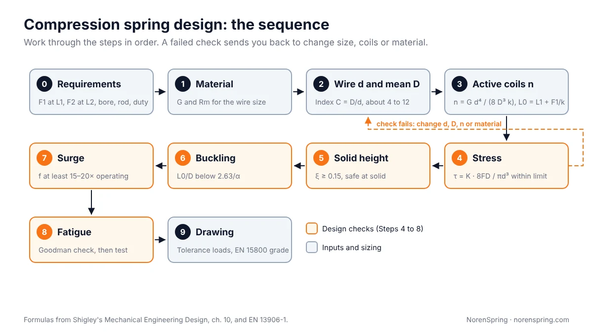
- The design sequence at a glance
- Step 1: Choose the material
- Step 2: Choose the wire diameter and mean coil diameter
- Step 3: Work out the active coils from the rate
- Step 4: Check shear stress with the stress correction factor
- Step 5: Check solid height and coil clearance
- Step 6: Check spring buckling
- Step 7: Check spring surge and natural frequency
- Step 8: Estimate fatigue life
- Step 9: Set tolerances and put it on the drawing
- Worked example: an agricultural machinery compression spring
- Compression spring design check calculator
- When to bring in a spring manufacturer
- Frequently asked questions
- About the authors
- Sources
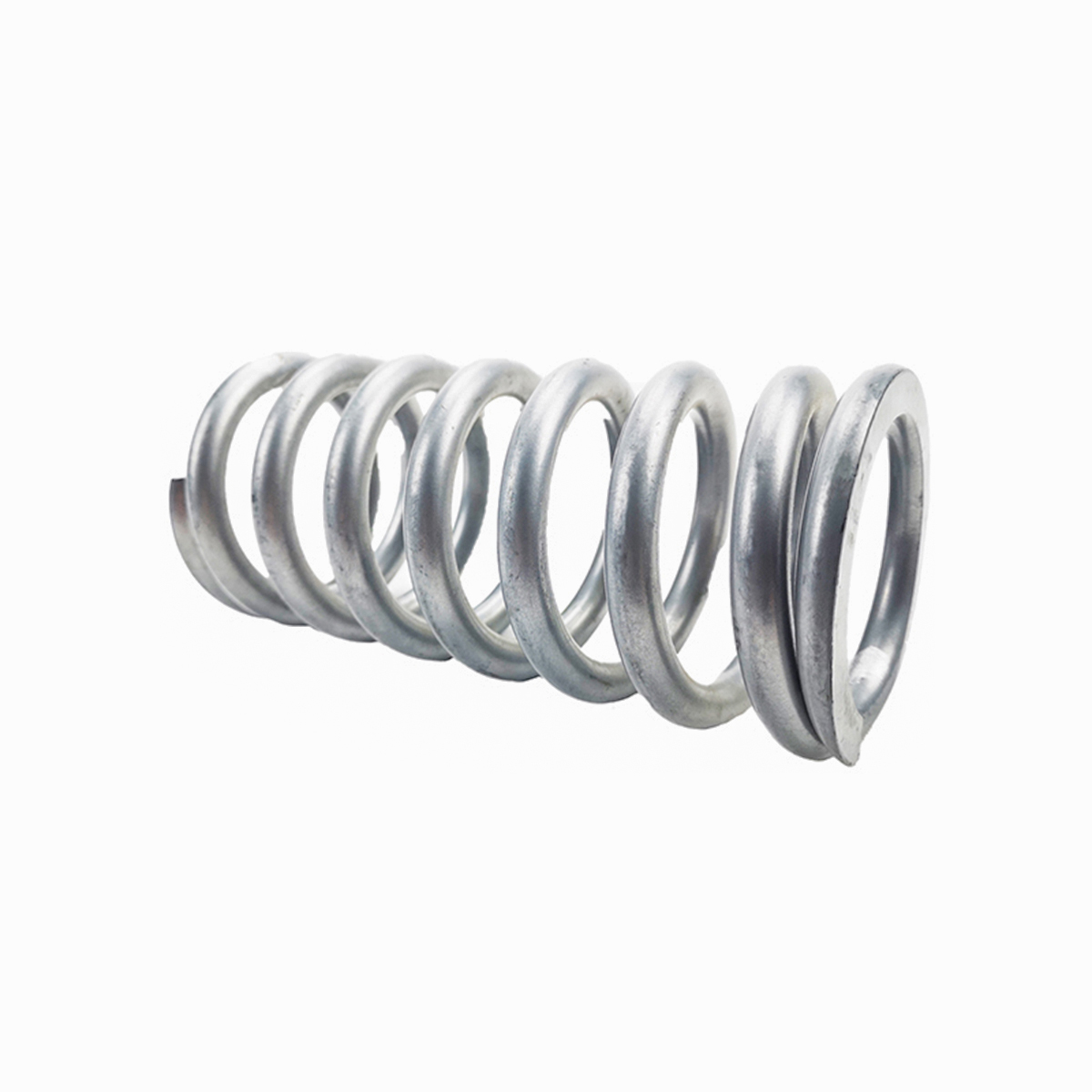
Compression spring design follows the same basic order every time. Start from the job: the force you need at two working lengths, the travel between them, and the space the spring has to fit in. Choose a material for the temperature, corrosion and cycle count. Pick a wire diameter and mean coil diameter with a spring index between about 4 and 12. Work out the number of active coils from the rate. Then check five things before the drawing is released: shear stress, solid height, buckling, surge and fatigue life. Finish by deciding which dimensions to tolerance and which to mark as reference.
This guide walks through helical compression spring design for round-wire springs, one of the most common types of springs in agricultural machinery, vehicles and industrial equipment. Each step gives the formula and the rule of thumb, and links to our deeper guides where a topic needs more room. A full worked example near the end runs one spring from the load requirement to the drawing. A design check calculator lets you try your own numbers.
Key takeaways
- Design from two load points, not one. A force at an installed length and a force at the working length fix the rate and the free length. One force on its own does not define a spring.
- The spring index sets most of what follows. Keep C = D/d between about 4 and 12. Below 4 the spring is hard to coil and highly stressed on the inside of the coil; above 12 it tangles and holds tolerances poorly.
- Rate goes with d⁴ and 1/D³. Small changes in wire or coil diameter change the rate a lot, so settle d and D before adjusting the coil count.
- Check stress at solid, not just at the working load. If the spring can be compressed to solid in assembly or by accident, it must survive that without taking a permanent set.
- Check buckling and surge early. A slender spring (free length more than about 2.6 times the mean diameter on pivoting ends) needs guidance. A spring cycled quickly needs a natural frequency at least 15 to 20 times the operating frequency.
Start with the job: loads, travel and space
Every compression spring design starts with the requirement, not with a spring size. Before choosing any dimension, write down:
| Input | What to record | Why it matters |
|---|---|---|
| Load at installed length | Force F1 at length L1 | Fixes the preload and, with the second point, the free length |
| Load at working length | Force F2 at length L2 | Fixes the rate k = (F2 − F1) / (L1 − L2) |
| Space | Hole (bore) diameter, rod or shaft diameter, length available | Limits the outside and inside diameter and the solid height |
| Duty | Static, occasional, or cycled; cycles per minute; required life | Decides the stress limit and whether a fatigue check is needed |
| Environment | Temperature, moisture, chemicals, cleanliness | Decides the material and finish |
| Assembly | Can the spring be pressed to solid during assembly or misuse? | Decides whether stress at solid must be safe |
If you only have one load, ask for the second one or for the travel. Two springs can give the same force at one length and behave completely differently at the next. Our guide on how to specify a custom compression spring lists everything a manufacturer needs for a quote.
Allow space for the coils to grow. A compression spring’s outside diameter increases slightly as it is compressed, so leave clearance between the spring and the bore, and between the inside diameter and any rod, instead of designing to a sliding fit.
The design sequence at a glance
The steps below run in order, but in practice you will loop back. A spring that fails the buckling check may need a larger coil diameter, which changes the rate, which changes the coil count.
Step 1: Choose the material
Choose the material for the environment and the duty first, because it sets both the stiffness (shear modulus G) and the strength (minimum tensile strength Rm) used in every later step.
| Material | Typical use | Shear modulus G (GPa) | Notes |
|---|---|---|---|
| Patented cold-drawn carbon spring wire (EN 10270-1 SH/DH, ASTM A227) | General industrial and agricultural springs | about 79 to 81.5 | Economical; needs a finish outdoors |
| Music wire (ASTM A228) | Small, highly stressed springs | about 80 to 82.7 | Highest strength in small sizes |
| Oil tempered and alloy wire (Cr-V, Cr-Si) | Higher temperature and fatigue duty, valve and engine springs | about 77.2 | Better relaxation resistance than cold-drawn wire |
| Stainless steel (302/304, 316) | Wet, food and medical environments | about 69 | Lower stiffness and strength than carbon wire |
| Phosphor bronze, beryllium copper | Electrical contacts, non-magnetic parts | about 41 (phosphor bronze) | Much softer; larger wire needed for the same rate |
Shear modulus values are from Shigley’s spring material table [1]. The EN 10270-1 datasheet value for SH/DH wire is about 81.5 GPa [5].
For stainless springs in drug-delivery and diagnostic devices, our medical spring manufacturer page covers materials, certification and the records we supply.
Strength falls as the wire gets thicker. For EN 10270-1 grade SH or DH wire, the minimum tensile strength is 1,980 MPa at 2 mm, 1,840 MPa at 3 mm, 1,740 MPa at 4 mm and 1,660 MPa at 5 mm [5]. Use the minimum value for the wire size you choose, not a single figure for the grade. Our spring wire material guide compares grades and their Chinese, European and American equivalents.
Step 2: Choose the wire diameter and mean coil diameter
Choose the wire diameter d and mean coil diameter D together, so that the spring fits the space and the spring index C = D/d sits in a workable range.
- Mean diameter D = outside diameter − d = inside diameter + d.
- Spring index C = D/d. Shigley recommends 4 ≤ C ≤ 12 for good manufacturability and stress [1]. EN 13906-1 accepts 4 to 20 for cold-coiled springs and 3 to 12 for hot-coiled springs [2], but springs at the high end of that range are harder to hold to tolerance and tend to tangle.
A good first guess is to take the largest mean diameter the space allows, then pick a wire diameter that gives C between 6 and 9. A larger D lowers the rate and the stress correction factor but raises the nominal stress, since τ rises with D. A larger d raises the rate steeply, and the stress falls with d³. Our spring index guide explains why the range matters and what to do outside it.
Step 3: Work out the active coils from the rate
Work out the rate you need from the two load points, then solve the rate formula for the number of active coils:
k = G · d⁴ / (8 · D³ · n), so n = G · d⁴ / (8 · D³ · k)
where k is the rate (N/mm), G the shear modulus (N/mm²), d the wire diameter (mm), D the mean coil diameter (mm) and n the number of active coils [1]. Round n to a practical value, usually to the nearest quarter coil, and recalculate k.
Then add the inactive end coils. For closed (squared) ends, whether ground or not, the total coils are n + 2 [1][3]. Shigley recommends at least 3 and no more than 15 active coils for a well-behaved spring [1].
Then set the free length from the first load point: L0 = L1 + F1 / k. Our spring rate guide covers the formula in detail, including springs in series and parallel and how rate is measured.
Step 4: Check shear stress with the stress correction factor
The wire of a compression spring is loaded in torsion. The basic shear stress is:
τ = 8 · F · D / (π · d³)
The inside of each coil is more highly stressed than this because of the wire’s curvature, so the stress is multiplied by a correction factor that depends on C. Two forms are in common use [1]:
- Wahl factor: K = (4C − 1)/(4C − 4) + 0.615/C
- Bergsträsser factor: K = (4C + 2)/(4C − 3), the form used in EN 13906-1 [2]
The two give almost the same value. At C = 7.5 the Wahl factor is 1.197 and the Bergsträsser factor 1.185.
Compare the stress with an allowable value expressed as a fraction of the wire’s minimum tensile strength Rm:
| Basis | Allowable static shear stress | Source |
|---|---|---|
| Music wire and cold-drawn carbon steel, corrected stress, set not removed | 45% of Rm | Shigley, Table 10-6 [1] |
| Hardened and tempered carbon and low-alloy steel, same basis | 50% of Rm | Shigley [1] |
| Austenitic stainless steel and non-ferrous alloys, same basis | 35% of Rm | Shigley [1] |
| Same materials after set removal (presetting), stress with the direct-shear factor Ks = 1 + 0.5/C only | 55% to 75% of Rm, depending on material | Shigley [1] |
| EN 13906-1, cold-coiled compression spring, uncorrected stress at solid length | about 56% of Rm | EN 13906-1 as reported by Hexagon [4] |
Use one method consistently. The textbook route checks the corrected stress against the lower limits; the EN route checks the uncorrected stress at solid against the higher limit. Both are conservative for static springs. For cycled springs, the static limit is not enough and you also need the fatigue check in Step 8.
Step 5: Check solid height and coil clearance
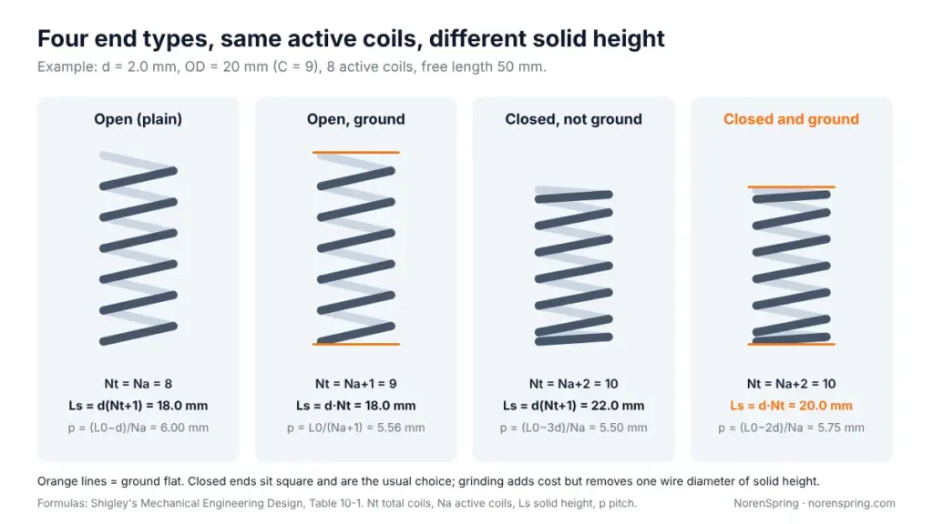
Solid height is the length when every coil touches. For closed and ground ends it is about the total coils times the wire diameter, n_t · d. For closed ends that are not ground it is about (n_t + 1) · d [1]. EN 15800 gives the maximum values a manufacturer must hold: n_t · d_max for ground ends and (n_t + 1.5) · d_max for unground ends [3].
Two checks follow:
- The working length must stay clear of solid. Shigley defines the fractional overrun to closure ξ, with the solid force equal to (1 + ξ) times the maximum working force, and recommends ξ ≥ 0.15 [1]. In practice, the maximum working deflection should be no more than about 85% to 87% of the deflection to solid. Near solid the rate rises as coils start touching, and the spring no longer behaves like the formula.
- The spring must survive being pressed to solid if that can happen in assembly or service. Calculate the force at solid, Fs = k (L0 − Ls), and check its stress against the limits in Step 4. If it fails, the usual fixes are a lower stress design, a mechanical stop that prevents full compression, or presetting (compressing the spring to solid after coiling so that it takes its set before delivery). Shigley notes that presetting is not recommended for springs subject to fatigue [1].
Step 6: Check spring buckling
A long, slender compression spring can bow sideways instead of compressing straight. Whether it does depends on the ratio of free length to mean diameter and on how the ends are held. For steel springs, Shigley gives the condition for absolute stability as L0 < 2.63 · D / α, where α is an end-condition constant [1]:
| End condition | α | Stable if L0/D is below |
|---|---|---|
| Both ends on flat, parallel surfaces (ends squared and ground) | 0.5 | 5.26 |
| One end on a flat surface, the other pivoted | 0.707 | 3.72 |
| Both ends pivoted | 1 | 2.63 |
| One end clamped, the other free | 2 | 1.31 |
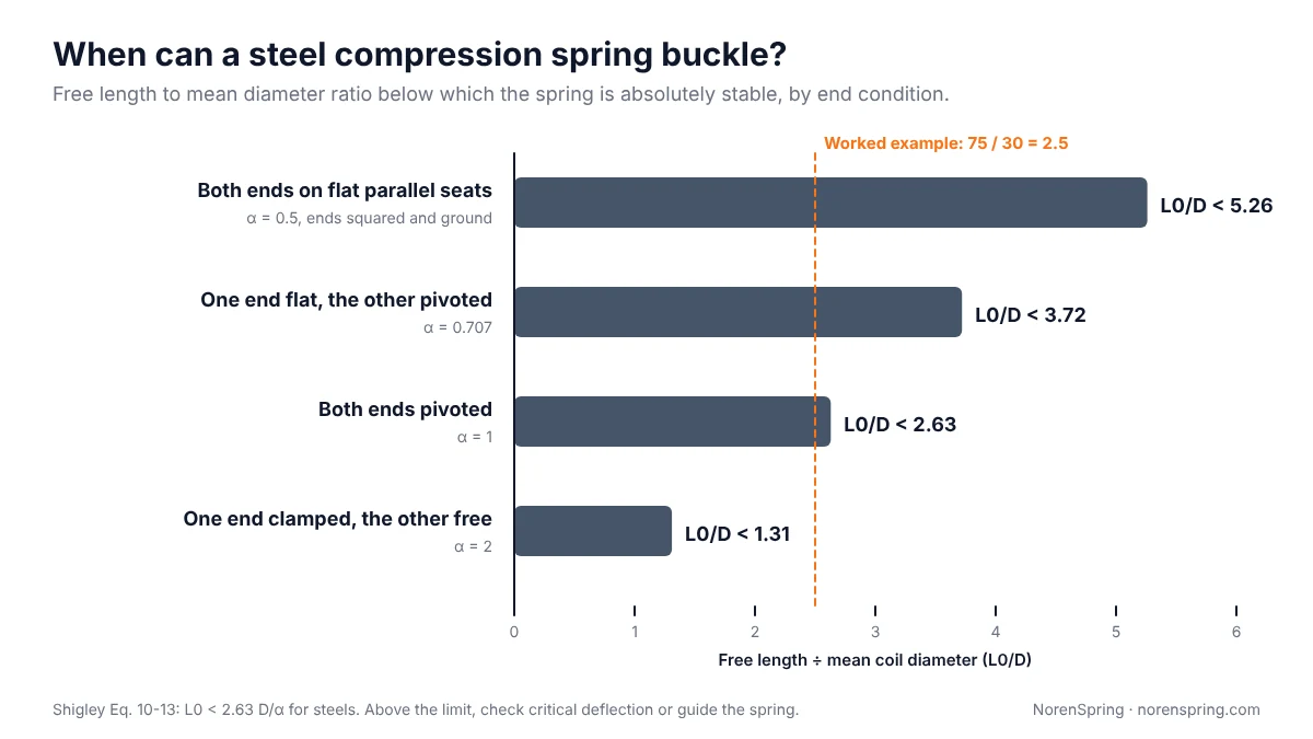
A spring above these limits is not certain to buckle. It may buckle before reaching its working length, and the full check uses the critical deflection formula in Shigley or the buckling diagram in EN 13906-1 [1][2]. When a slender spring cannot be avoided, guide it over a rod or inside a tube. Leave clearance for the coil diameter to grow, and expect some friction and wear on the guide.
Step 7: Check spring surge and natural frequency
Spring surge is a resonant wave travelling along the coils. It occurs when the operating frequency approaches the spring’s natural frequency: the coils clash and the stress rises far above what the static calculation predicts. Valve springs in over-revved engines are the classic case [1].
For a steel compression spring between two flat plates, the first natural frequency is approximately:
f ≈ 3.63 × 10⁵ · d / (n · D²) Hz, with d and D in mm
This comes from Shigley’s f = ½ √(k g / W), where W is the weight of the active coils, written out for steel with G about 81.5 GPa and density 7.85 kg/dm³ [1]. Shigley recommends that the natural frequency be at least 15 to 20 times the frequency of the force or motion applied to the spring [1]. To raise it, increase the rate or reduce the spring’s mass, usually with a smaller coil diameter and fewer coils.
This check matters for vibrator springs on vibrating screens, for springs on cams and linkages, and for any spring driven by an engine or motor.
Step 8: Estimate fatigue life
A spring that cycles between two loads fails by fatigue long before it reaches its static stress limit, so a dynamic spring needs a separate check. EN 13906-1 treats a spring as dynamically loaded when it sees more than 10⁴ cycles with a meaningful stress range, and defines infinite life as at least 10⁷ cycles for cold-coiled springs [2].
The usual textbook method splits the load into a mean and an alternating part [1]:
- Fm = (F2 + F1) / 2 and Fa = (F2 − F1) / 2
- τm and τa are calculated from Fm and Fa with the corrected stress formula
These are then compared with the wire’s endurance data on a Goodman diagram. For steel spring wire under 10 mm, Zimmerli’s data give an infinite-life endurance strength of 241 MPa alternating at 379 MPa mean for unpeened springs, and 398 MPa at 534 MPa for shot-peened springs [1]. The torsional ultimate strength is estimated as 0.67 Rm when no test data exist [1].
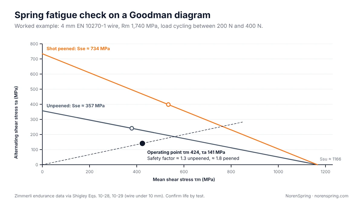
Shot peening puts compressive stress in the wire surface. In Zimmerli’s data the infinite-life point rises from 241 MPa to 398 MPa alternating stress, and in the worked example below the fatigue safety factor rises from about 1.3 to 1.8 [1]. A fatigue estimate is still only an estimate. EN 13906-1 says service life under variable load must be verified by a fatigue test [2]. Ask your manufacturer which tests they can run on samples. Our spring manufacturing process guide explains where stress relief, shot peening and presetting fit in production.
Step 9: Set tolerances and put it on the drawing
A compression spring cannot be held to tight tolerances on every dimension at once, because coil count, free length and rate are linked. Tolerance the dimensions that matter to your assembly and let the manufacturer adjust the others.
EN 15800, which replaced DIN 2095, sets tolerances for cold-coiled compression springs in three quality grades. It covers wire from 0.07 mm to 16 mm, mean diameter from 0.63 mm to 200 mm, free length up to 630 mm, at least 2 active coils and index 4 to 20 [3]. It gives tolerances for coil diameter, free length, the spring force at a stated length, and the squareness and parallelism of ground ends [3].
A good drawing for a custom compression spring shows:
| On the drawing | Status |
|---|---|
| Material and standard (e.g. EN 10270-1 DH, ASTM A228, SUS304) | Required |
| Wire diameter d | Reference, if the force is toleranced |
| Outside or inside diameter, whichever fits the assembly | Toleranced |
| Free length L0 | Toleranced, or reference if two loads are given |
| Force F1 at length L1, force F2 at length L2 | Toleranced (the functional requirement) |
| Total coils, active coils, direction of wind | Reference |
| End type (closed and ground, closed, open) | Required |
| Solid height, maximum | Required if space is tight |
| Squareness and parallelism of ends | If the spring must stand or seat squarely |
| Finish, shot peening, presetting, cleanliness | As required |
| Tolerance standard and grade (e.g. EN 15800 grade 2) | Recommended |
The common practice is to tolerance one or two forces and let the manufacturer adjust the free length, or the coil count, to hit them. If you also tolerance the free length and coil count tightly, you are asking for three things that cannot all be held at once.
Worked example: an agricultural machinery compression spring
This example runs the steps for a return spring in an agricultural implement. Our compression spring case studies show real parts of this kind. The numbers are illustrative but every result can be recalculated with the formulas above.
Requirement. 200 N (45 lbf) at an installed length of 60 mm (2.36 in); 400 N (90 lbf) at the working length of 45 mm (1.77 in), giving 15 mm of travel. The spring sits in a 38 mm (1.50 in) bore over a 20 mm (0.79 in) rod. It cycles slowly, at no more than 2 Hz, and must last for a long service life outdoors.
Step 1, material. EN 10270-1 grade DH carbon spring wire, zinc plated and baked after plating to reduce the risk of hydrogen embrittlement (see our spring finishes guide). G = 81,500 MPa. For 4 mm wire, Rm min = 1,740 MPa [5].
Step 2, size. The rate needed is (400 − 200) / (60 − 45) = 13.33 N/mm. Try d = 4 mm and D = 30 mm, so C = 7.5, outside diameter 34 mm and inside diameter 26 mm. That leaves 4 mm diametral clearance to the bore and 6 mm to the rod.
Step 3, coils. n = 81,500 × 4⁴ / (8 × 30³ × 13.33) = 7.24. Use 7.25 active coils, which gives k = 13.32 N/mm. With closed and ground ends, total coils = 9.25. Free length L0 = 60 + 200 / 13.32 = 75.0 mm. Check: at 45 mm the force is 13.32 × 30 = 400 N.
Step 4, stress at working load. Uncorrected stress at 400 N: 8 × 400 × 30 / (π × 4³) = 477 MPa. Bergsträsser factor at C = 7.5 is 1.185, so the corrected stress is 566 MPa, which is 33% of Rm. That is well within the 45% limit.
Step 5, solid. Solid height ≈ 9.25 × 4 = 37 mm. Deflection to solid is 75 − 37 = 38 mm; the maximum working deflection is 30 mm, which is 79% of it (ξ = 0.27, above 0.15). Force at solid is 13.32 × 38 = 506 N. Uncorrected stress at solid is 605 MPa, or 35% of Rm, below the EN limit of about 56%. Corrected, it is 716 MPa, or 41% of Rm, below the 45% textbook limit. The spring survives being pressed to solid without presetting, although the margin on the textbook basis is under the 1.2 safety factor Shigley suggests [1]. A designer who expects frequent overtravel would add a stop.
Step 6, buckling. L0/D = 75 / 30 = 2.5. That is below 2.63, so the spring is stable even with pivoting ends, and comfortably so with ground ends on flat seats. The rod is not needed for stability.
Step 7, surge. f ≈ 3.63 × 10⁵ × 4 / (7.25 × 30²) = 222 Hz. That is more than 100 times the 2 Hz operating frequency.
Step 8, fatigue. The load cycles between 200 N and 400 N, so Fm = 300 N and Fa = 100 N. Corrected stresses: τm = 424 MPa and τa = 141 MPa. With Zimmerli’s unpeened data and the Goodman line, the fatigue safety factor is about 1.3. With shot peening it rises to about 1.8. Either is acceptable for a first design, to be confirmed by a fatigue test on samples.
Step 9, drawing. EN 10270-1 DH, d = 4 mm (ref), OD 34 mm, L0 75 mm (ref), F1 = 200 N ± tolerance at 60 mm, F2 = 400 N ± tolerance at 45 mm, 9.25 total coils (ref), right-hand wind (ref), closed and ground ends, maximum solid height about 37.3 mm (9.25 × the maximum wire diameter within the wire tolerance), zinc plated with hydrogen relief after plating, tolerances to EN 15800 grade 2.
Compression spring design check calculator
Enter your spring’s dimensions to run the checks in Steps 3 to 7. The default values are the worked example above. Inputs are metric: 1 in = 25.4 mm, 1 lbf = 4.448 N.
Compression spring design check
Round-wire helical compression spring, steel or stainless. Checks rate, stress at the working length and at solid, overrun to solid, buckling and natural frequency.
Estimates from textbook formulas (Shigley, chapter 10): Bergsträsser stress correction, allowable static stress 45% of Rm for carbon wire, 50% for oil tempered and alloy wire and 35% for stainless (set not removed), overrun to solid ξ ≥ 0.15, buckling limit L0 < 2.63 D/α, natural frequency between flat plates. They do not replace a fatigue check or a test on samples.
When to bring in a spring manufacturer
Bring a manufacturer in once you have the two load points, the space and a first-pass design, and before the drawing is frozen. A spring maker can tell you whether the index, tolerances and end type can be made economically in your quantity. They can suggest a wire size you can actually buy, and make samples so you can check load, fit and life in the real assembly.
NorenSpring works from a drawing, a sketch or a physical sample, confirms manufacturability before quoting, and replies with engineering feedback within 24 hours. Our wire range runs from 0.1 mm to 80 mm, we have no fixed minimum order quantity, and we supply prototype and pre-production samples for load and fit approval. See our custom compression springs and capabilities.
Send your design for review See compression springs
Frequently asked questions
How do you design a compression spring?
Start with two forces at two lengths, plus the bore, rod and length available. Choose a material, then a wire diameter and mean coil diameter that give a spring index of about 4 to 12. Calculate the active coils from n = G d⁴ / (8 D³ k), add two inactive coils for closed ends, and set the free length from the first load point. Then check stress, solid height, buckling, surge and fatigue, and loop back if any check fails.
What is a good spring index for design?
Between 4 and 12, and ideally 6 to 9. Below 4 the wire is bent too sharply to coil easily and the stress correction factor is high. Above 12 the spring is floppy, tangles in handling and is hard to hold to diameter and length tolerances. EN 13906-1 permits up to 20 for cold-coiled springs, but higher values cost more to hold to tolerance.
How do I stop a compression spring from buckling?
Keep the free length below about 5.3 times the mean diameter for ground ends on flat parallel seats, or 2.6 times for pivoting ends. If the spring must be longer, guide it over a rod or inside a tube with clearance for the coils to grow. You can also split it into two shorter springs with a guided washer between them, or use a larger coil diameter.
What is spring surge?
Spring surge is a wave that travels along the coils when a spring is driven near its natural frequency. The coils bunch up and clash, the force becomes erratic and the stress can be much higher than the static calculation shows. Avoid it by keeping the spring’s natural frequency at least 15 to 20 times the operating frequency. For a steel spring between flat plates, f ≈ 3.63 × 10⁵ · d / (n · D²) Hz, with d and D in mm.
How much of the deflection to solid can I use?
Keep the maximum working deflection to about 85% to 87% of the deflection to solid, which is close to Shigley’s overrun-to-closure guideline of ξ ≥ 0.15. Beyond that, coils start to touch, the rate rises and the force becomes less predictable. The spring should also be able to reach solid without taking a set if that can happen in assembly or service.
About the authors
This guide was prepared by the NorenSpring engineering team, which designs and manufactures custom compression, extension and torsion springs and wire forms in Xuzhou, China. Technical review by Feng Yulin, General Manager and senior structural engineer, who has 15 years of spring R&D experience and more than 30 national patents. NorenSpring holds IATF 16949, ISO 9001, ISO 13485, ISO 14001 and ISO 45001 certifications. More about NorenSpring. Formulas and figures were last checked on October 15, 2026.
Sources
The numbers in square brackets in the text refer to this list.
- R. G. Budynas and J. K. Nisbett, Shigley’s Mechanical Engineering Design, 9th edition, McGraw-Hill, 2011, chapter 10 (Mechanical Springs): equations 10-1 to 10-33 and tables 10-1, 10-2, 10-5 and 10-6. Source for the rate and stress formulas, the Wahl and Bergsträsser factors, recommended index, coil count and overrun to closure, the allowable stress percentages (from Joerres, Standard Handbook of Machine Design), the buckling condition L0 < 2.63 D/α, the natural frequency formula and 15 to 20 times rule, and Zimmerli’s endurance data. The same equations appear in later editions.
- CEN, EN 13906-1:2013, Cylindrical helical springs made from round wire and bar. Calculation and design. Part 1: Compression springs. Source for the index ranges (4 to 20 cold coiled, 3 to 12 hot coiled), the stress correction factor, the definition of dynamic loading and infinite life, and the requirement to verify fatigue life by test. Retrieved 2026-10-15.
- CEN, EN 15800:2008, Cylindrical helical springs made of round wire. Quality specifications for cold coiled compression springs. Source for the scope, the toleranced parameters and the solid length limits. DIN Media confirms that DIN 2095 was replaced by DIN EN 15800. Retrieved 2026-10-15.
- Hexagon Industriesoftware, Newsletter info179, January/February 2020 (F. Ruoss). Source for the permissible stress of 56% of Rm for compression springs under EN 13906; check against the standard itself for critical designs. Retrieved 2026-10-15.
- EN 10270-1, Steel wire for mechanical springs. Part 1: Patented cold drawn unalloyed spring steel wire. Tensile strength values for grades SH and DH and the shear modulus of about 81.5 GPa as reproduced in Stahl-Becker GmbH, Patented Drawn Spring Steel Wire (SH/DH) datasheet. Retrieved 2026-10-15.